FC8600-UM-251-9370 8-1
8 TROUBLESHOOTING
8 TROUBLESHOOTING
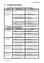
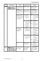
8.1 The Plotter is Turned On But Doesn’t Operate
Symptom
Verification item
Solution
Both USER1 and USER2
lamp on the control panel
does not light.
Nothing is displayed on
the LCD panel.
(1) Is the plotter being supplied with
power?
No .....Check that the power cord is
securely connected to the plotter’s
AC line inlet.
Yes ....Verify item (2).
(2)
Is the FFC707102 flexible cable
securely connected to the main
board and the control panel?
No .....
Connect the flexible cable
securely.
Yes ....Verify item (3).
(3)
Is the FFC707102 flexible cable
broken?
No .....Verify item (4).
Yes ....
Replace the FFC707102 flexible
cable.
(4) Is the AC line electrical output
correct?
No .....Change the AC line.
Yes ....Verify item (5).
(5) Does the power supply unit
have a 40 V output?
No .....Replace the power supply unit.
Yes ....Replace the main board.
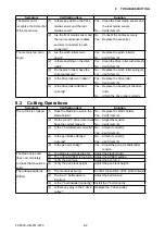
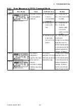
8.2 Media Loading Operations
Symptom
Verification item
Solution
The media drops to the
front of the plotter.
(1) Is the front edge of the media
curled?
Yes ....Replace the media.
No .....Verify item (2).
(2) Is the front media sensor dirty? Yes ....Clean the front media sensor.
No .....Verify item (3).
(3) Is the front media sensor cable
securely connected to the main
board and the sensor?
Yes ....Replace the front media sensor.
No .....Connect the cable securely.
The media drops to the
rear of the plotter.
(1) Is the rear edge of the media
curled?
Yes ....Replace the media.
No .....Verify item (2).
(2) Is the rear media sensor dirty? Yes ....Clean the rear media sensor.
No .....Verify item (3).
(3) Is the rear media sensor cable
securely connected to the main
board and the sensor?
Yes ....Replace the rear media sensor.
No .....Connect the cable securely.
The plotter displays
“LOAD MEDIA!” when
media has been loaded.
(1) Does the cam sensor plate
block the cam sensor?
Yes ....Check the cam sensor plate and
attach it at the correct position.
No .....Verify item (2).
(2) Is the cam sensor cable
securely connected to the main
board and the sensor?
No .....Connect the cable securely.
Yes ....Replace the cam sensor board.
The plotter can’t
recognize the Y direction
of the media size.
(1) Is there any dust on the pinch
roller sensor?
Yes ....Clean the pinch roller sensor.
No .....Verify item (2).
(2)
Is the pinch roller sensor flexible
cable securely connected to
each connector?
Yes ....Replace the pinch roller sensor.
No .....Connect the cable securely.
Содержание FC8600-100
Страница 1: ...CUTTING PLOTTER SERVICE MANUAL FC8600 60 75 100 130 160 FC8600 UM 251 07 9370 ...
Страница 2: ......
Страница 4: ...FC8600 UM 251 9370 II ...
Страница 32: ......
Страница 103: ...FC8600 UM 251 9370 7 43 7 ADJUSTMENT ...
Страница 118: ...FC8600 UM 251 9370 8 15 8 TROUBLESHOOTING 11 When testing is completed turn off the power to the plotter ...
Страница 124: ...FC8600 UM 251 9370 9 2 9 PARTS LIST Outer Casing 4 6 2 3 9 13 11 12 14 15 10 1 16 8 7 5 ...
Страница 131: ...FC8600 UM 251 9370 9 9 9 PARTS LIST Main Frame 1 3 4 5 7 8 9 10 11 12 6 2 15 16 13 14 20 21 22 17 18 19 ...
Страница 141: ...FC8600 UM 251 9370 10 3 10 BLOCK DIAGRAMS AND CIRCUIT DIAGRAMS 10 2 2 Main Board CONNECTOR ...
Страница 142: ...FC8600 UM 251 9370 10 4 10 BLOCK DIAGRAMS AND CIRCUIT DIAGRAMS 10 2 3 Main Board MOTOR DRIVER ...
Страница 143: ...FC8600 UM 251 9370 10 5 10 BLOCK DIAGRAMS AND CIRCUIT DIAGRAMS 10 2 4 Main Board FPGA ...
Страница 144: ...FC8600 UM 251 9370 10 6 10 BLOCK DIAGRAMS AND CIRCUIT DIAGRAMS 10 2 5 Main Board I F ...
Страница 145: ...FC8600 UM 251 9370 10 7 10 BLOCK DIAGRAMS AND CIRCUIT DIAGRAMS 10 2 6 Main Board MEMORY ...
Страница 146: ...FC8600 UM 251 9370 10 8 10 BLOCK DIAGRAMS AND CIRCUIT DIAGRAMS 10 2 7 Main Board Power When the LAN is connected ...
Страница 147: ...FC8600 UM 251 9370 10 9 10 BLOCK DIAGRAMS AND CIRCUIT DIAGRAMS 10 2 8 LAN Board ...
Страница 148: ...FC8600 UM 251 9370 10 10 10 BLOCK DIAGRAMS AND CIRCUIT DIAGRAMS 10 2 9 Light Pointer ...
Страница 149: ...FC8600 UM 251 9370 10 11 10 BLOCK DIAGRAMS AND CIRCUIT DIAGRAMS 10 2 10Pen Relay Board ...
Страница 151: ...FC8600 UM 251 9370 10 13 10 BLOCK DIAGRAMS AND CIRCUIT DIAGRAMS 10 2 13Control Panel Board ...
Страница 152: ...FC8600 UM 251 9370 10 14 10 BLOCK DIAGRAMS AND CIRCUIT DIAGRAMS 10 2 14Cam Sensor Board ...

