FC8600-UM-251-9370 7-42
7 ADJUSTMENT
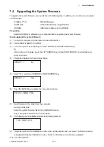
7.4 Upgrading the System Firmware
To upgrade the system firmware you need to have the following files. In addition, you need to use a computer
and USB cable.
• FC8600_V***.X
:FC8600 firmware
• SEND.EXE
:Utility to transfer files using Windows
®
• OPS662
:USB Driver software for the FC8600
Preparation
Install the USB Driver software to your computer before upgrading the system firmware.
How to upgrade the system firmware
(1) Connect the computer and the plotter via the USB interface.
(2) Load a sheet of paper in the plotter.
(3) Turn on the power while pressing the LEFT ARROW and RIGHT ARROW keys.
Or
After turning on the power, press the LEFT ARROW key and the RIGHT ARROW key simultaneously
within 2 seconds.
(4) The plotter displays the menu shown below.
UPDATE ? No
(5) Select “Yes” using the UP ARROW or DOWN ARROW key.
UPDATE ? Yes
(6) Press the ENTER key to display the menu shown below.
PLEASE SEND PRG.
(7)
Send firmware to the plotter from the computer.
Execute SEND.EXE.
Select the system firmware file from the SEND.EXE menu.
Output the system firmware file to the FC8600.
(8) The following menu is displayed while data is being received.
**KB RECEIVED
(9)
The plotter will start the initialization routine when all the data has been received. The firmware version
is displayed during the initialization routine. Check the firmware version that you upgraded.
(10) Turn off the power.
Содержание FC8600-100
Страница 1: ...CUTTING PLOTTER SERVICE MANUAL FC8600 60 75 100 130 160 FC8600 UM 251 07 9370 ...
Страница 2: ......
Страница 4: ...FC8600 UM 251 9370 II ...
Страница 32: ......
Страница 103: ...FC8600 UM 251 9370 7 43 7 ADJUSTMENT ...
Страница 118: ...FC8600 UM 251 9370 8 15 8 TROUBLESHOOTING 11 When testing is completed turn off the power to the plotter ...
Страница 124: ...FC8600 UM 251 9370 9 2 9 PARTS LIST Outer Casing 4 6 2 3 9 13 11 12 14 15 10 1 16 8 7 5 ...
Страница 131: ...FC8600 UM 251 9370 9 9 9 PARTS LIST Main Frame 1 3 4 5 7 8 9 10 11 12 6 2 15 16 13 14 20 21 22 17 18 19 ...
Страница 141: ...FC8600 UM 251 9370 10 3 10 BLOCK DIAGRAMS AND CIRCUIT DIAGRAMS 10 2 2 Main Board CONNECTOR ...
Страница 142: ...FC8600 UM 251 9370 10 4 10 BLOCK DIAGRAMS AND CIRCUIT DIAGRAMS 10 2 3 Main Board MOTOR DRIVER ...
Страница 143: ...FC8600 UM 251 9370 10 5 10 BLOCK DIAGRAMS AND CIRCUIT DIAGRAMS 10 2 4 Main Board FPGA ...
Страница 144: ...FC8600 UM 251 9370 10 6 10 BLOCK DIAGRAMS AND CIRCUIT DIAGRAMS 10 2 5 Main Board I F ...
Страница 145: ...FC8600 UM 251 9370 10 7 10 BLOCK DIAGRAMS AND CIRCUIT DIAGRAMS 10 2 6 Main Board MEMORY ...
Страница 146: ...FC8600 UM 251 9370 10 8 10 BLOCK DIAGRAMS AND CIRCUIT DIAGRAMS 10 2 7 Main Board Power When the LAN is connected ...
Страница 147: ...FC8600 UM 251 9370 10 9 10 BLOCK DIAGRAMS AND CIRCUIT DIAGRAMS 10 2 8 LAN Board ...
Страница 148: ...FC8600 UM 251 9370 10 10 10 BLOCK DIAGRAMS AND CIRCUIT DIAGRAMS 10 2 9 Light Pointer ...
Страница 149: ...FC8600 UM 251 9370 10 11 10 BLOCK DIAGRAMS AND CIRCUIT DIAGRAMS 10 2 10Pen Relay Board ...
Страница 151: ...FC8600 UM 251 9370 10 13 10 BLOCK DIAGRAMS AND CIRCUIT DIAGRAMS 10 2 13Control Panel Board ...
Страница 152: ...FC8600 UM 251 9370 10 14 10 BLOCK DIAGRAMS AND CIRCUIT DIAGRAMS 10 2 14Cam Sensor Board ...

