Advanced Functions and Settings
♦
C4 - 22
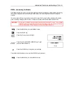
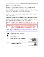
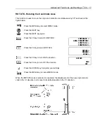
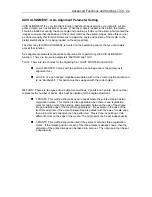
AXIS ALIGNMENT - Axis Alignment Parameter Setting
AXIS ALIGNMENT is a very important function that should be used when you intend to cut pre-
printed media, such as stickers or decals. When the media is loaded in the plotter, the media
should be loaded at exactly the same angle and position as it was on the printer which printed the
images to ensure that the position of the contour matches the printed images. Since this can not
be done manually, this function allows one to adjust the angle and position of the media on the
plotter electrically as if it is being loaded on the same printer.
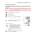
The direct key for AXIS ALIGNMENT is located on the operation panel so that you can rapidly
access that function.
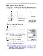
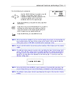
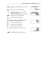
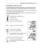
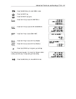
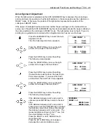
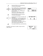
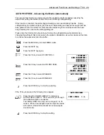
Axis Alignment parameters should be configured prior to performing the AXIS ALIGNMENT
function. There are two main parameters: METHOD and TOOL
TOOL: There are two choices for the digitizing tool, LIGHT POINTER and LOUPE.
n
LIGHT POINTER: Comes with the plotter’s pen carriage and is the primary axis
alignment tool.
n
LOUPE: Is a pen shaped magnifier associated with a cross cursor (optional) referred
to as “Bombsight”. This option must be swapped with the cutter holder.
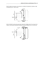
METHOD: There are two types of axis alignment methods, 2 points and 3 points. Each number
represents the number of points, which will be digitized for the angle adjustment.
n
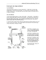
2 POINTS: This method should be used in cases where the printed media has two
registration marks. This method is also applicable when there is one registration
mark for origin point of the printing, and parallelism between the axis of the printed
image and side edge of the media are guaranteed. For example in the case of the
tractor feed printer, if the axis of printed image is parallel with the axis of media edge
then a 2 points axis alignment can be performed. This is done by pointing at two
different points on the edge of the media. The origin point can be set independently.
n
3 POINTS: This method should be used if the printed media has three registration
marks. If the relative position of each of the three marks is already known, then the
distortion of the printed image can be taken into account. The origin point can be set
independently.
Содержание Cutting Pro FC4100-100
Страница 1: ...cutting pro FC4100 series series USER S MANUAL 1 a...
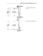
Страница 77: ...Advanced Functions and Settings C4 15 Setting a negative expansion limit Setting a positive expansion limit...
Страница 138: ...Setting the Interface Functions C7 7 Input Output Circuitry Input Output Timing Chart...
Страница 146: ...Specifications C8 5 External Dimensions FC4100 75 without Stand FC4100 75 with Stand and Basket Option...
Страница 147: ...Specifications C8 6 FC4100 100 without Stand FC4100 100 with Stand Standard and Basket Option...
Страница 148: ...Specifications C8 7 FC4100 130 without Stand FC4100 130 with Stand Standard and Basket Option...
Страница 169: ...The specifications etc in this manual are subject to change without notice Printed in U S A Part No 53801 072T Rev B asd...

