

Setting the Interface Functions
♦
C7 - 10
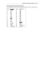
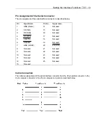
Pin Assignment of the Serial Connector
The pin assignment of the serial interface connector is described below.
Pin
No.
Signal Name
Pin No.
Signal name
1
GND (Frame)
14
Not used
2
SD (TxD)
15
Not used
3
RD (RxD)
16
Not used
4
RS (RTS)
17
Not used
5
CS(CTS)
18
Not used
6
DR(DSR)
19
Not used
7
GND (LOGIC)
20
ER (DTR)
8
Not used
21
Not used
9
Not used
22
Not used
10
Not used
23
Not used
11
Not used
24
Not used
12
Not used
25
Not used
13
Not used
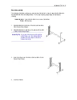
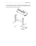
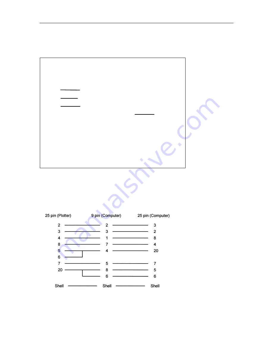
Cable Connection
The cable pin assignment of the serial interface connector from the 25 pin plotter connector to the
9 pin computer connector or the 25 pin computer connector is described below.
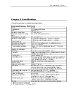
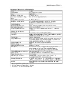
Содержание Cutting Pro FC4100-100
Страница 1: ...cutting pro FC4100 series series USER S MANUAL 1 a...
Страница 77: ...Advanced Functions and Settings C4 15 Setting a negative expansion limit Setting a positive expansion limit...
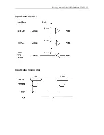
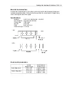
Страница 138: ...Setting the Interface Functions C7 7 Input Output Circuitry Input Output Timing Chart...
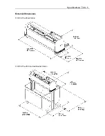
Страница 146: ...Specifications C8 5 External Dimensions FC4100 75 without Stand FC4100 75 with Stand and Basket Option...
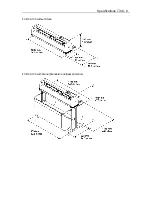
Страница 147: ...Specifications C8 6 FC4100 100 without Stand FC4100 100 with Stand Standard and Basket Option...
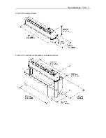
Страница 148: ...Specifications C8 7 FC4100 130 without Stand FC4100 130 with Stand Standard and Basket Option...
Страница 169: ...The specifications etc in this manual are subject to change without notice Printed in U S A Part No 53801 072T Rev B asd...