6-6
Chapter 6 Troubleshooting
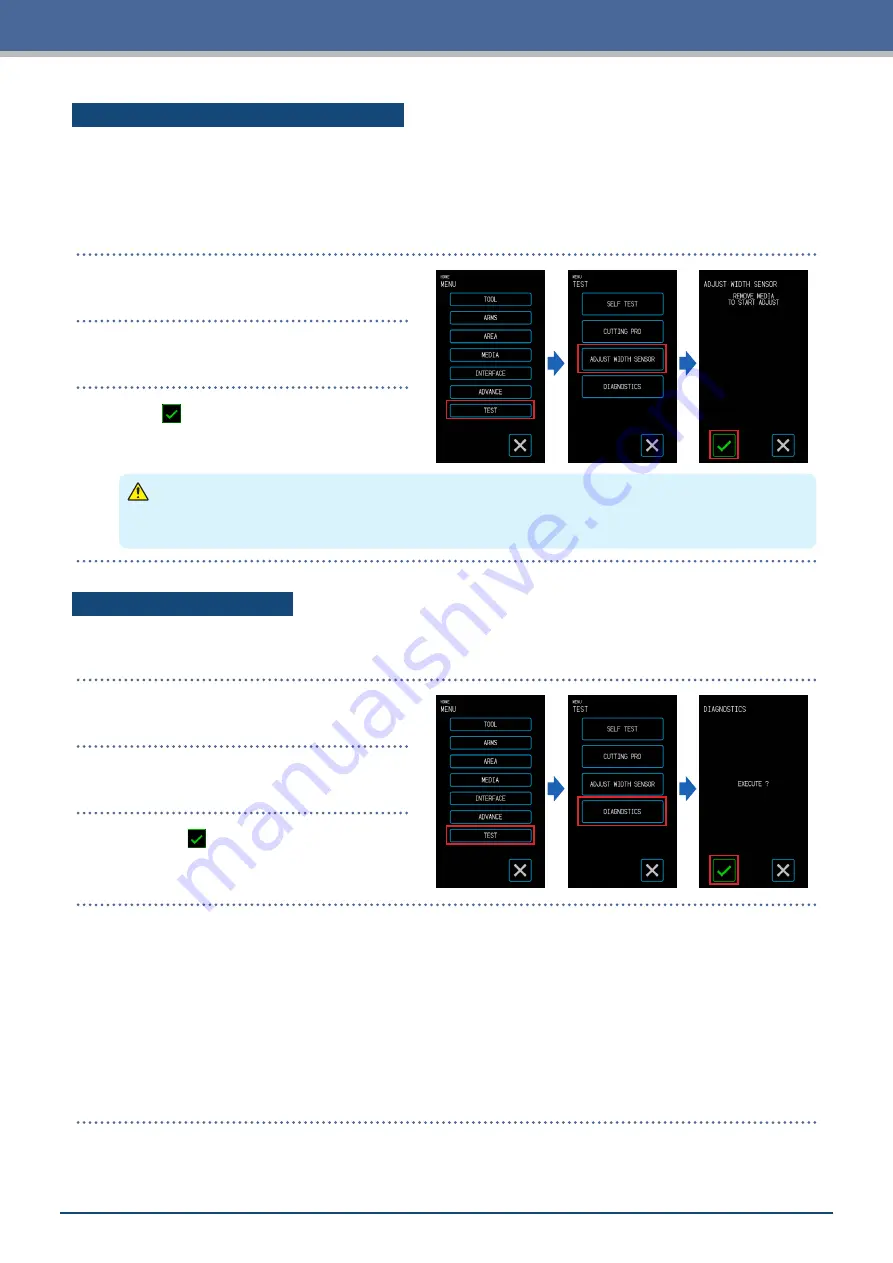
Adjusting the Width Detection Sensor
This device uses the width detection sensor to detect the leading edge/ width/ position of the media.
Adjust the width detection sensor if errors related to the leading edge/ width/ position occur with media that
could be loaded without any problem.
Remove the media before adjusting the width detection sensor. It cannot be adjusted correctly when media is
loaded.
1.
From the "MENU" screen, select "TEST"
screen.
2.
Select "ADJUST WIDTH SENSOR".
3.
When (Execute) is touched, adjustment
of width detection sensor will start.
CAUTION
When the "Execute" is touched, the media and tool carriage will start moving. Be careful to avoid contact
with your body or any object.
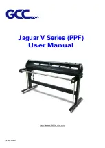
Main Unit Diagnosis Test
The operating status of the device can be checked by following instructions on the screen to operate each of
the sensors and switches.
1.
From the "MENU" screen, open the "TEST"
screen.
2.
Touch the "DIAGNOSTICS".
3.
When the (Execute) is touched,
messages for the test will appear on the
screen.
4.
Operate the sensors and levers by following the instructions displayed on the screen.
Touch the (Next) on the screen for each test item to proceed to the next test item. Touch the (Exit) to exit
the main unit diagnosis and return to the "TEST" screen.
Test Items
"Media Sensor" – "Home Sensor" – "Raising and Lowering of the Tool" – "Intake Fan" – "Registration
Mark LED" – "Media Set Levers"
The tests consist of detections of the operating status in relation to operations and visual confirmations.
For items subject to detection, "OK" will appear on the screen when detection is normal.
Once all test items have been completed, the system will return to the "TEST" screen.
Содержание CELITE-50
Страница 1: ...USER S MANUAL CE LITE 50 UM 151...
Страница 2: ......
Страница 10: ......
Страница 22: ......
Страница 78: ......
Страница 101: ...5 23 Chapter 5 Detailed Settings 3 Select ON or OFF for WIDTH DETECTION...
Страница 112: ......
Страница 116: ...A 4 Appendix A 3 Appearance Drawing 164 784 227 173 400 Units mm Dimension error 5 mm...
Страница 118: ...A 6 Appendix 3 PIECES Previous Page HOME SELECT FILE...
Страница 119: ...A 7 Appendix TOOL ARMS MODE 1 MODE 2 MODE 3 CHECK MARK SCAN SENSOR OFFSET ADJ Next Page MENU...
Страница 120: ...A 8 Appendix INTERFACE ADVANCE TEST Previous Page AREA MEDIA MENU...
Страница 127: ......
Страница 128: ......


