


8.
Save all shipping materials. They must be reinstalled any time
washer is moved more than four feet.
IMPORTANT: Do not lift or transport unit from front
or without shipping materials installed. Refer to the
Maintenace section for proper instructions on rein-
stalling the shipping materials.
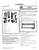
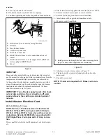
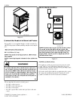
Connect Fill Hoses
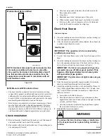
WARNING
Under certain conditions, hydrogen gas may be pro-
duced in a hot water system that has not been used
for two weeks or more. HYDROGEN GAS IS EXPLO-
SIVE. If the hot water system has not been used for
such a period and before using the washer, turn on
all hot water faucets and let the water flow from each
for several minutes. This will release any accumula-
ted hydrogen gas. The gas is flammable. Do not
smoke or use an open flame during this time.
W029
Water Supply Requirements
Water supply faucets must fit standard 19 mm [3/4 inch] female
garden hose couplings. DO NOT USE SLIP-ON OR CLAMP-
ON CONNECTIONS.
NOTE: Water supply faucets should be readily accessi-
ble to permit turning them off when washer is not being
used.
Recommended cold water temperature is 10° to 24° Celsius [50°
to 75° Fahrenheit]. Recommended maximum hot water tempera-
ture is 51° Celsius [125° Fahrenheit]. Warm water is a mixture of
hot and cold water. Warm water temperature is dependent upon
the water temperature and the pressure of both the hot and cold
water supply lines.
WARNING
To prevent personal injury, avoid contact with inlet
water temperatures higher than 51° Celsius [125°
Fahrenheit] and hot surfaces.
W748
Maximum flow rate for all water temperatures is 9.46 liters per
minute [2.5 gallons per minute] ± 15%.
Water pressure must be a minimum of 138 to a maximum of 827
kPa [minimum of 1.4 bar to a maximum of 8.3 bar] static pres-
sure measured at the faucet.
NOTE: Water pressure under 138 kPa [20 pounds per
square inch] will cause an extended fill time in the
washer and may not properly flush out the detergent
dispenser.
The appliance is to be connected to the water mains using new
hose-sets and the old hose-sets should not be reused.
Turn on the water supply faucets and flush the lines for approxi-
mately two minutes to remove any foreign materials that could
clog the screens in the water mixing valve. This is especially im-
portant when installing your washer in a newly constructed or
renovated building. Build-up may have occurred during construc-
tion.
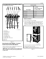
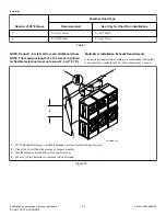
Model Numbers Ending in "06"
Connecting Hoses
To comply with water regulations, this washing machine must be
fitted with an approved 3/4 inch double check valve to both the
hot and cold supplies between shut off valve and fill hose. Refer
to
.
Maximum water flow rate to the dispenser is 10 liters per minute.
Installation Notice: Note that the Machines must be installed with
Double Check Valves at the Faucets which are not supplied.
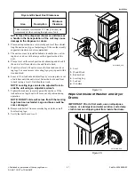
1.
Insert rubber washers and filter screens (from accessories
bag) in water fill hose couplings (two hoses supplied with
washer). The filter screen must be facing outward.
NOTE: If using hoses with BSPP thread coupling, in-
sert filter screens into the BLACK colored hose cou-
plings and the rubber washers into the brass col-
ored hose couplings.
2.
Connect fill hose couplings with filter screens to water supply
faucets.
3.
Connect the other hose couplings to the hot and cold valve
connections at the rear of the washer.
NOTE: If using hoses with BSPP thread coupling,
connect the BLACK colored hose coupling end of
the fill hoses (with filter screens) to the water supply
faucets. Then connect end of hoses with the brass
colored hose couplings to the hot and cold water
mixing valve connections at rear of washer.
4.
Thread hose couplings onto valve connections finger tight.
Then turn 1/4 turn with pliers.
IMPORTANT: DO NOT cross thread or overtighten
couplings. This will cause them to leak.
5.
Turn water on and check for leaks.
6.
If leaks are found, retighten the hose couplings.
7.
Continue tightening and rechecking until no leaks are found.
Installation
©
Published by permission of the copyright owner -
DO NOT COPY or TRANSMIT
16
Part No. 805898ENR1


