background image

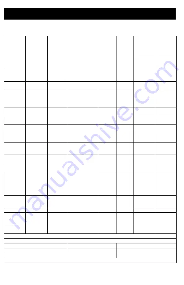
Accessories and Labels 

48

3A6491E

Accessories and Labels

Sprayer 

Model

Ref. 34

Card, 

Medical 

Alert 

Ref. 46

Hose, 1/4 

in. x 50 ft

Ref. 52

Label, 

Front,

Upper/

Lower

Ref. 53

Label, 

Side

Ref. 61

Gun, 

Spray

Ref. 63

Label, 

Warning

Ref. 65

Label, 

Warning

826243

826244

826245

222385 #

826079

17E947/17E945

17E948

826252

15H085 #

195793 &

826246

826247

826248

222385 #

826079

17E947/17E949

17E951

826252

15H085 #

195793 &

826249

826250

222385 #

826079

17E947/17E952

17E954

826252

15H085 #

195793 &

826258

826259

222385 #

826079

17E947/19Y232

19Y231

826252

15H085 #

195793 &

19Y128

19Y129

222385 #

240794

17E944/19Y232

19Y233

17Y042

15H085 #

195793 &

19Y359

19Y361

222385 #

240794

17E944/19Y232

19Y233

17Y043

n/a

n/a

19Y360

19Y362

222385 #

240794

17E944/19Y232

19Y233

17Y043

n/a

n/a

19Y424

17A134 

240794

17E944/19Y232

19Y233

17Y044 15H087 @ 195792 @

17E852

17E853

17E854

222385 #

240794

17E944/17E945

17E946

17Y042

15H085 #

195793 &

17E855

17E856

17E857

222385 #

240794

17E944/17E949

17E950

17Y042

15H085 #

195793 &

17E858

17E859

222385 #

240794

17E944/17E952

17E953

17Y042

15H085 #

195793 &

17E864

17E865

222385 #

240794

17E967/17E969

17E970

17Y043

17E871

17E872

17E873

17E874

17E875

17E870

222385 #

240794

17E967/17E949

17E971

17Y043

n/a

n/a

17E876

17E877

17E878

222385 #

240794

17E967/17E952

17E972

17Y043

n/a

n/a

17E887

17A134 

240794

17E944/17E945

17E946

17Y044 15H087 @ 195792 @

17E889

17E891

17E892

17A134 

240794

17E944/17E949

17E950

17Y044 15H087 @ 195792 @

17E896

17E897

17A134 

240794

17E944/17E952

17E953

17Y044 15H087 @ 195792 @

288526 – Kit, accessory, hopper

# – English, Spanish, French

@ – Asia/ANZ

 – English, Chinese, Korean

 – Europe

& – North America

* – Japan

Replacement safety labels, tags, and cards are available at no cost.

Содержание ST MAX II 395 PC Pro

Страница 1: ...22 8 MPa Maximum Working Pressure See page 3 for additional model information Important Safety Instructions Read all warnings and instructions in this manual in related manuals and on the unit before using the equipment Be familiar with the controls and the proper usage of the equipment Save these instructions Related Manuals Gun 3A6285 Contractor PC Pump 334599 Use only genuine Graco replacement ...

Страница 2: ...tal Display 23 BlueLink App 25 Enabling or Disabling BlueLink 25 Maintenance 26 Recycling and Disposal at End of Life 26 Troubleshooting 27 Mechanical Fluid Flow 27 Electrical 30 490 495 395EU Stand Sprayers 38 490 495 595 Lo Boy Sprayers 40 650 Lo Boy Sprayer 42 490 495 595 395EU Hi Boy Sprayers 44 650 Hi Boy Sprayer 46 Accessories and Labels 48 Control Box 50 Battery Replacement 52 Wiring Diagra...

Страница 3: ...650 PC Pro 826259 826258 230 CEE 7 7 ST MAX II 395 PC Pro 17E864 17E865 ST MAX II 495 PC Pro 17E871 17E874 ST MAX II 595 PC Pro 17E876 230 Europe Multi ST MAX II 495 PC Pro 17E872 17E875 ST MAX II 595 PC Pro 17E877 Ultra Max II 650 PC Pro 19Y361 19Y359 110 UK ST MAX II 495 PC Pro 17E873 17E870 ST MAX II 595 PC Pro 17E878 Ultra Max II 650 PC Pro 19Y362 19Y360 230 Asia ANZ Ultra MAX II 490 PC Pro 17...

Страница 4: ...r replacement of the cord or plug is required do not connect the grounding wire to either flat blade terminal The wire with insulation having an outer surface that is green with or without yellow stripes is the grounding wire Check with a qualified electrician or serviceman when the grounding instructions are not completely understood or when in doubt as to whether the product is properly grounded...

Страница 5: ...ers unless they are anti static or conductive Connect to a grounded outlet and use grounded extensions cords Do not use a 3 to 2 adapter Do not use a paint or a solvent containing halogenated hydrocarbons Do not spray flammable or combustible liquids in a confined area Keep spray area well ventilated Keep a good supply of fresh air moving through the area Sprayer generates sparks Keep pump assembl...

Страница 6: ...e of producing 3300 psi Use Graco replacement parts or accessories that are rated a minimum of 3300 psi Always engage the trigger lock when not spraying Verify the trigger lock is functioning properly Verify that all connections are secure before operating the unit Know how to stop the unit and bleed pressure quickly Be thoroughly familiar with the controls EQUIPMENT MISUSE HAZARD Misuse can cause...

Страница 7: ...t with aluminum Contact your material supplier for compatibility MOVING PARTS HAZARD Moving parts can pinch cut or amputate fingers and other body parts Keep clear of moving parts Do not operate equipment with protective guards or covers removed Equipment can start without warning Before checking moving or servicing equipment follow the Pressure Relief Procedure and disconnect all power sources TO...

Страница 8: ...sure Control D Prime Valve F Tip Guard G Spray Tip H Gun J Airless Hose K Power Cord L Trigger Lock M Drain Tube N Suction Tube P Pump R Fluid Outlet S Power Cord Wrap U Filter V Finger Guard TSL Fill Point W BlueLink Status Light if applicable Model Serial Tag Not shown located on bottom of unit ...

Страница 9: ...e Control D Prime Valve F Tip Guard G Spray Tip H Gun J Airless Hose K Power Cord L Trigger Lock M Drain Tube N Suction Tube P Pump R Fluid Outlet U Filter V Finger Guard TSL Fill Point W BlueLink Status Light if applicable Model Serial Tag Not shown located on bottom of unit ...

Страница 10: ...D Prime Valve F Tip Guard G Spray Tip H Gun J Airless Hose K Power Cord L Trigger Lock M Drain Tube N Suction Tube P Pump R Fluid Outlet S Hanger T Filter U Finger Guard TSL Fill Point V Pail Hook W BlueLink Status Light if applicable Model Serial Tag Not shown located on bottom of unit ...

Страница 11: ...longer extension cords may reduce sprayer performance Pails Solvent and oil based fluids follow local code Use only conductive metal pails placed on a grounded surface such as concrete Do notplacepailona non conductive surface such as paper or cardboard which interrupts grounding continuity Always ground a metal pail connect a ground wire to the pail Clamp one end to the pail and the other end to ...

Страница 12: ... down drain position until you are ready to spray again 5 Hold a metal part of the spray gun firmly to a grounded metal pail Point spray gun into pail Disengage the trigger lock and trigger the spray gun to relieve pressure This equipment stays pressurized until pressure is manually relieved To help prevent serious injury from pressurized fluid such as skin injection splashed fluid and moving part...

Страница 13: ...or tip obstruction Trigger Lock Always engage the trigger lock when sprayer is stopped to prevent the gun from being triggered accidentally by hand or if dropped or bumped Setup When unpacking sprayer for the first time or after long term storage perform setup procedure When first setup is performed remove shipping plug from fluid outlet 1 Connect Graco airless hose to fluid outlet Use wrenches to...

Страница 14: ...ll throat packing nut with TSL to preventprematurepacking wear Do this daily or each time you spray a Place the TSL bottle nozzle into the top center opening in the grill at the front of the sprayer b Squeeze bottle to dispense enough TSL to fill the space between the pump rod and packing nut seal 8 Make certain ON OFF switch is OFF 9 Plug power supply cord into a properly grounded electrical outl...

Страница 15: ...be in grounded metal pail partially filled with flushing fluid Use water to flush water based paint or mineral spirits to flush oil based paint 20 Turn ON OFF switch to ON position 21 Turn prime valve horizontal Disengage trigger lock 22 Hold a metal part of the gun firmly to a grounded metal pail Trigger gun and flush until clean 23 Turn ON OFF switch to OFF position 24 Engage trigger lock 25 Spr...

Страница 16: ...switch to ON position 4 Place fluid intake in paint pail Place drain tube in waste pail 5 Turn pressure control to Fast Flush to start motor Allow paint to circulate through drain tube for 15 seconds 6 Turn prime valve horizontal Disengage trigger lock 7 Hold gun against grounded metal waste pail Trigger gun until paint appears ...

Страница 17: ...sure Relief Procedure page 12 then tighten all fittings and repeat Startup procedure If there are no leaks continue with the next step 10 Screw tip assembly onto gun and tighten See Spray Tip Installation page 18 For gun assembly instructions see separate gun manual High pressure spray is able to inject toxins into the body and cause serious bodily injury Do not stop leaks with hand or rag ...

Страница 18: ...ne Finish Low Pressure reversible spray tip is used spraying pressure can be lowered Spraying at a lower pressure results in less over spray and reduces spray tip wear Adjust the sprayer pressure to minimize overs pray To avoid serious injury from skin injection do not put your hand in front of the spray tip when installing or removing the spray tip and tip guard ti24653a C B A ti24664a Atomized e...

Страница 19: ...by 50 4 Trigger gun after moving Release trigger before stopping For additional spraying information see separate gun manual Clear Spray Tip Clog 1 Release trigger Engage trigger lock Rotate Spray Tip Disengage trigger lock Trigger gun at waste area to clear clog 2 Engage trigger lock Return Spray Tip to original position Disengage trigger lock and continue spraying ti24669a ti24673a To avoid inju...

Страница 20: ...d intake and drain tube from paint wipe excess paint off outside 4 Place fluid intake in flushing fluid Use water for water base paint and mineral spirits for oil based paint Place drain tube in waste pail 5 To flush drain tube and pump turn prime valve down 6 Turn pressure control to Fast Flush operate until the pump runs steady and flushing fluid appears in the waste pail ti24709a ti24710a ...

Страница 21: ...waste pail Disengage trigger lock Trigger gun and turn pressure control to Fast Flush operate until the pump runs steady and flushing fluid appears 9 Stop triggering gun 10 Raise fluid intake above flushing fluid 11 With prime valve horizontal Trigger gun into flushing pail to purge fluid from hose 12 Engage trigger lock ti24714a ...

Страница 22: ...yer 14 Remove filter from gun and sprayer if installed Clean and inspect Install filter See separate gun manual 15 If flushing with water flush again with mineral spirits or Pump Armor to leave a protective coating to prevent freezing or corrosion 16 Wipe sprayer hose and gun with a rag soaked in water or mineral spirits ...

Страница 23: ...Dashes appear when pressure is less than 200 psi 14 bar 1 4 MPa 4 Short press display button to move to Job Gallons or Liters x 10 NOTE JOB displays briefly then the number of gallons sprayed above 1000 psi 70 bar 7MPa 5 Press and hold display button to reset to zero or short press button to move to Lifetime Gallons or Liters x10 NOTE LIFE displays briefly then the number of gallons sprayed above ...

Страница 24: ...er Short press display button and the total motor run hours is displayed 4 Short press display button and the last error code is displayed e g E 07 See Electrical page 30 for trouble shooting information 5 Press and hold display button to clear error code to zero Short press to move to software REV 6 Turn ON OFF switch to OFF position to exit Stored Data ti24644a ti7489b ti7490b ti7491b ti24586a ...

Страница 25: ...e app Instructions can also be accessed online at https www graco com BlueLinkSupport Enabling or Disabling BlueLink The Graco BlueLink system uses Bluetooth to communicate between the sprayer s control board and a mobile phone To disable BlueLink by shutting off the Bluetooth transmitter perform the following steps 1 Turn the ON OFF switch to the OFF position Turn the Pressure Control Knob all th...

Страница 26: ...on the control board Recycle according to applicable regulations Do not dispose of electronic components with household or commercial waste Deliver remaining product to a recycling facility Activity Interval Inspect clean sprayer filter fluid inlet strainer and gun filter Daily or each time you spray Inspect motor shield vents for blockage Daily or each time you spray Fill TSL by adding through TS...

Страница 27: ...sure Check and clean spray tip Paint supply Refill and reprime pump Intake strainer clogged Remove and clean then reinstall Intake valve ball and piston ball are not seating properly Remove intake valve and clean Check balls and seats for nicks replace if necessary See pump manual Strain paint before using to remove particles that could clog pump Fluid filter or tip filter is clogged or dirty Clea...

Страница 28: ...pump manual Replace connecting rod assembly See pump manual Gears or drive housing damaged Inspect drive housing assembly and gears for damage and replace if necessary Excessive paint leakage into throat packing nut Throat packing nut is loose Remove throat packing nut spacer Tighten throat packing nut just enough to stop leakage Throat packings are worn or damaged Replace packings See pump manual...

Страница 29: ...rn Replace pump packings See pump manual Paint is too thick Thin the paint according to supplier recommendations Sprayer operates for 5 to 10 minutes then stops Pump packing nut too tight When pump packing nut is too tight the packings on the pump rod restrict pump action and overloads the motor Loosen pump packing nut Check for leaks around throat If necessary replace pump packings See Pump manua...

Страница 30: ...bserve the status light Blinking LED total count equals the error code for example two blinks equals CODE 02 Error Code Messages Keep clear of electrical and moving parts during troubleshooting procedures To avoid electrical shock hazards when covers are removed for troubleshooting wait 5 minutes after disconnecting power cord for stored electricity to dissipate CODE MESSAGE ACTION 02 HIGH PRESSUR...

Страница 31: ...logs such as clogged filter Use airless paint spray hose with no metal braid A small hose or metal braid hose may result in high pressure spikes Turn ON OFF switch OFF and disconnect power to sprayer Check transducer and connections to control board Disconnect transducer from control board socket Check that transducer and control board contacts are clean and secure Reconnect transducer to control ...

Страница 32: ... not run Check transducer resistance with an ohmmeter less than 9k ohm between red and black wires and 3 6k ohm between green and yellow wires Sprayer does not run at all AND Control board status light blinks 5 times repeatedly Control is commanding motor to run but motor shaft does not rotate Possibly locked rotor condition an open connection exists between motor and control there is a problem wi...

Страница 33: ...Pin 4 the green wire is not used in this test If all spin test is positive continue to step 6 6 Perform Field Short Test Test at large 4 pin motor field connector There should not be continuity from pin 4 the ground wire and any of the remaining 3 pins If motor field connector tests fail replace motor 7 Reconnect motor connector s to control board socket s Connect power turn ON OFF switch ON and c...

Страница 34: ...e sure contacts are clean and secure Measure resistance of the thermal device If reading is not correct replace motor Check Motor Thermal Switch Unplug thermal wires Set meter to ohms Meter should read 100k ohms 3 Reconnect thermal device connector to control board socket Connect power turn sprayer ON and control knob 1 2 turn clockwise If sprayer does not run replace control board Basic electrica...

Страница 35: ...Troubleshooting 3A6491E 35 Electrical cont Sprayer Will Not Run See following page for steps ...

Страница 36: ...Troubleshooting 36 3A6491E ...

Страница 37: ...rocedure Plumb pressure gauge into paint hose plug sprayer in and turn power switch ON Does sprayer reach or exceed its maximum pressure Mechanical problem See the proper fluid pump manual for the sprayer for further troubleshooting procedures Is the control board status light on NO Replace the control board NO Replace the control board NO YES YES Unplug the transducer from control board Does moto...

Страница 38: ...490 495 395EU Stand Sprayers 38 3A6491E 490 495 395EU Stand Sprayers 1 2 See page 50 4 3 2 Ref Torque 140 160 in lb 15 8 18 1 N m 23 27 in lb 2 6 3 0 N m Hammer Tight 20 30 ft lb 33 9 40 7 N m 1 2 3 4 1 ...

Страница 39: ... 1 47 117493 SCREW mach hex washer hd 13 52 See page 48 LABEL front upper lower 1 53 See page 48 LABEL side 1 54 MOTOR includes 1 8 9 10 125 126 1 287805 490 495 395EU 55 246381 HOSE drain stand includes 39 62 1 57 276897 STRAINER 7 8 14 unf 1 59 19Y413 KIT frame standmount Includes 67 1 60 246386 KIT hose suction includes 14 57 62 1 61 See page 48 GUN spray not shown 1 62 276888 CLIP drain line 1...

Страница 40: ...490 495 595 Lo Boy Sprayers 40 3A6491E 490 495 595 Lo Boy Sprayers See page 50 2 1 1 4 3 2 1 Ref Torque 140 160 in lb 15 8 18 1 N m 23 27 in lb 2 6 3 0 N m Hammer Tight 20 30 ft lb 33 9 40 7 N m 1 2 3 4 ...

Страница 41: ...sher hd 12 52 See page 48 LABEL front upper lower 1 53 See page 48 LABEL side 1 54 MOTOR includes 1 8 9 10 125 126 1 287805 Models 490 495 287807 Model 595 55 246381 HOSE drain stand includes 39 62 1 57 276897 STRAINER 7 8 14 unf 1 59 246250 FRAME cart lo 1 60 246386 KIT hose suction includes 14 57 62 1 61 See page 48 GUN spray not shown 1 62 276888 CLIP drain line 1 63 See page 48 LABEL warning 1...

Страница 42: ...650 Lo Boy Sprayer 42 3A6491E 650 Lo Boy Sprayer Ref Torque 140 160 in lb 15 8 18 1 N m 30 35 in lb 3 4 4 0 N m Hammer Tight 20 30 ft lb 33 9 40 7 N m 1 2 3 4 2 1 1 3 4 See page 50 ...

Страница 43: ...52 See page 48 LABEL front 1 53 See page 48 LABEL side 1 54 287807 MOTOR includes 1 8 9 10 125 126 1 55 248217 HOSE drain stand includes 39 1 57 112604 STRAINER 1 59 24Y424 FRAME cart lo 1 60 248216 KIT hose suction 1 61 See page 48 GUN spray not shown 1 62 15D000 CLIP drain line 1 63 See page 48 LABEL warning 1 64 16G596 LABEL warning Europe 1 65 See page 48 LABEL warning 1 67 109032 SCREW mach 4...

Страница 44: ... Hi Boy Sprayers 44 3A6491E 490 495 595 395EU Hi Boy Sprayers See page 50 Ref Torque 140 160 in lb 15 8 18 1 N m 30 35 in lb 3 4 4 0 N m 23 27 in lb 2 6 3 0 N m Hammer tight 25 30 ft lb 33 9 40 7 N m 1 2 3 4 5 3 2 1 4 5 ...

Страница 45: ...7807 595 55 287952 HOSE drain includes 39 1 57 276897 STRAINER 7 8 14 UNF 1 59 17C485 FRAME cart hi 1 60 17C992 KIT stinger tube includes 14 57 84 91 96 61 See page 48 GUN spray not shown 1 62 276888 CLIP drain line 1 63 See page 48 LABEL warning 1 64 16G596 LABEL warning Europe 1 65 See page 48 LABEL warning 1 67 109032 SCREW mach pan hd 4 69 287489 HANDLE assembly hi cart 1 70 17C483 COVER pump ...

Страница 46: ...0 Hi Boy Sprayer 46 3A6491E 650 Hi Boy Sprayer Ref Torque 140 160 in lb 15 8 18 1 N m 30 35 in lb 3 4 4 0 N m 23 27 in lb 2 6 3 0 N m Hammer tight 25 30 ft lb 33 9 40 7 N m 1 2 3 4 5 1 3 4 2 5 See page 50 ...

Страница 47: ... front upper lower 1 53 See page 48 LABEL side 1 54 287807 MOTOR includes 1 8 9 10 125 126 1 55 287952 HOSE drain includes 39 1 57 112604 STRAINER 1 59 17C485 FRAME cart hi 1 60 19Y309 KIT stinger tube includes 14 1 61 See page 48 GUN spray not shown 1 62 15D000 CLIP drain line 1 63 See page 48 LABEL warning 1 64 16G596 LABEL warning Europe 1 65 See page 48 LABEL warning 1 67 109032 SCREW pan hd 4...

Страница 48: ...3 17Y043 n a n a 19Y424 17A134 240794 17E944 19Y232 19Y233 17Y044 15H087 195792 17E852 17E853 17E854 222385 240794 17E944 17E945 17E946 17Y042 15H085 195793 17E855 17E856 17E857 222385 240794 17E944 17E949 17E950 17Y042 15H085 195793 17E858 17E859 222385 240794 17E944 17E952 17E953 17Y042 15H085 195793 17E864 17E865 222385 240794 17E967 17E969 17E970 17Y043 17E871 17E872 17E873 17E874 17E875 17E87...

Страница 49: ...Notes 3A6491E 49 Notes ...

Страница 50: ...Control Box 50 3A6491E Control Box 3 1 4 Ref Torque 140 160 in lb 15 8 18 1 N m 20 25 in lb 2 3 2 8 N m 37 43 ft lb 50 2 58 3 N m 130 150 in lb 14 7 16 9 N m 1 2 3 4 1 2 ...

Страница 51: ...V 490 495 models US Japan includes 19 17Z261 120V 595 models US Japan includes 19 17Z262 230V 490 495 595 models 17Z263 110V UK 490 495 595 models 19Y365 120V 650 Model 19Y382 230V 650 models 19Y383 110V 650 models 49 17P731 LABEL pressure adjustment w FastFlush 1 50 COVER control 1 17Y568 BlueLink 56 CORD power 1 253367 US 490 495 models 253371 US 595 650 models 253378 Japan 253373 Multicord Asia...

Страница 52: ...Battery Replacement 52 3A6491E Battery Replacement BlueLink Units Only ...

Страница 53: ...Wiring Diagrams 3A6491E 53 Wiring Diagrams 110 120V Models 395EU 490 495 595 ...

Страница 54: ...95 NOTICE Heat from inductor coil of filter board may destroy wire insulation that comes in contact with it Exposed wires could cause shorts and component damage Bundle and tie loose wires so none lay in contact with inductor coil on the filter board ...

Страница 55: ...Wiring Diagrams 3A6491E 55 120V 110V Model 650 ...

Страница 56: ...TICE Heat from inductor coil of filter board may destroy wire insulation that comes in contact with it Exposed wires could cause shorts and component damage Bundle and tie loose wires so none lay in contact with inductor coil on the filter board ...

Страница 57: ...Notes 3A6491E 57 Notes ...

Страница 58: ...U 490 495 720 per gallon 190 per liter 595 620 per gallon 164 per liter 650 570 per gallon 150 per liter Generator Minimum 395EU 490 3500 W 495 3750 W 595 650 4000 W Power Requirements 395EU 490 1Ø 50 60 Hz 110 120V 12 A 220 240V 7 A 495 1Ø 50 60 Hz 110 120V 15 A 220 240V 9 A 595 650 1Ø 50 60 Hz 110 120V 15 A 220 240V 9 A Dimensions Height Stand 18 5 in 47 0 cm Lo Boy 490 495 395EU 595 22 5 in 57 ...

Страница 59: ...Pa 4 8 bar Sound pressure 90 dBa Sound power 100 dBa Materials of Construction Wetted materials on all models zinc and nickel plated carbon steel nylon stainless steel PTFE acetal leather UHMWPE aluminum tungsten carbide polyethylene fluoroelastomer urethane Notes Startup pressures and displacement per cycle may vary based on suction condition discharge head air pressure and fluid type Sound press...

Страница 60: ...received including interference that may cause undesired operation Changes or modifications not expressly approved by the party responsible for compliance could void the user s authority to operate the equipment This equipment is not granted protection against harmful interference and cannot cause interference on systems properly authorized This equipment has the board BGM13P22A with homologation ...

Страница 61: ...s of parts labor and transportation THIS WARRANTY IS EXCLUSIVE AND IS IN LIEU OF ANY OTHER WARRANTIES EXPRESS OR IMPLIED INCLUDING BUT NOT LIMITED TO WARRANTY OF MERCHANTABILITY OR WARRANTY OF FITNESS FOR A PARTICULAR PURPOSE Graco s sole obligation and buyer s sole remedy for any breach of warranty shall be as set forth above The buyer agrees that no other remedy including but not limited to inci...

Страница 62: ...Information For the latest information about Graco products visit www graco com For patent information see www graco com patents TO PLACE AN ORDER contact your Graco distributor or call 1 800 690 2894 to identify the nearest distributor ...

Страница 63: ...Graco Information 3A6491E 63 ...

Страница 64: ...hanges at any time without notice Original instructions This manual contains English MM 3A6491 Graco Headquarters Minneapolis International Offices Belgium China Japan Korea GRACO INC AND SUBSIDIARIES P O BOX 1441 MINNEAPOLIS MN 55440 1441 USA Copyright 2018 Graco Inc All Graco manufacturing locations are registered to ISO 9001 www graco com Revision E November 2019 ...

Отзывы: