background image

Warnings

334625B

5

Installation

Mix manifold 17D763 is intended for use as a spray package or remote mounted manifold. It has a through check 
flushing feature that provides for an independent flush of resin and catalyst components from upstream of the fluid 
check valves. This ensures a clean flush and minimal maintenance from mixed material build up within the manifold.

The 24W861 manifold provides a more durable manifold for remote and portable manifold applications. It can be 
easily disassembled for cleaning or manifold porting and check valves. 

For assistance in setting up a plural component system, you should contact your Graco distributor. This will help 
ensure that you select the proper type and size of equipment for your job.

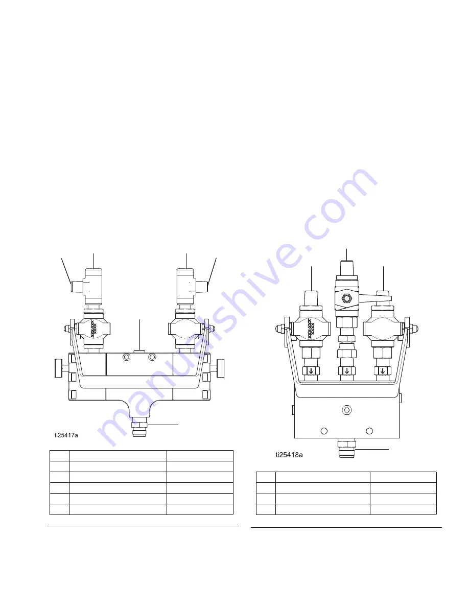
Connection Inlets

M2K Manifold 17D763

Remote 2K Manifold 24W861

F

IG

. 1 M2K Manifold

B

A

E

F

C

D

A

A Component Fluid Inlet

1/4” NPT (m)

B

B Component Fluid Inlet

1/4” NPT (m)

C

A Gauge Port

1/4” NPT (f)

D

B Gauge Port

1/4” NPT (f)

E

Solvent Inlet Port

1/4” NPT (f)

F

Fluid Outlet Port

3/8” NPSM (m)

F

IG

. 2 Remote 2K Manifold

A

A Component Fluid Inlet

1/4” NPT (m)

B

B Component Fluid Inlet

1/4” NPT (m)

C

Solvent Inlet Port

1/4” NPT

D

Fluid Outlet Port

3/8” (m)

A

B

C

D

Содержание M2K 17D763

Страница 1: ...e only Part 17D763 M2K manifold Part 24W861 Remote M2K manifold See page 2 for model information including maximum working pressure Important Safety Instructions Read all warnings and instructions in this man ual and in the M2K Spray Packages Instruc tions Parts manual Save all instructions Part No 17D763 Part No 24W861 ...

Страница 2: ... 11 Isolate a Mixing Problem 11 Parts 13 Part No 17D763 for M2K Proportioner 13 Part No 24W861 Remote Mix Manifold for M2K Proportioner 14 Notes 16 Technical Data 17 Graco Standard Warranty 18 Related Manuals Models Manual Description 333309 M2K Spray Packages Instructions Parts Part No Maximum Working Pressure psi bar MPa Description 17D763 3000 206 8bar 20 68 MPa Mechanical 2K Manifold 24W861 30...

Страница 3: ...urn power or light switches on or off when flammable fumes are present Ground all equipment in the work area See Grounding instructions Use only grounded hoses Hold gun firmly to side of grounded pail when triggering into pail If there is static sparking or you feel a shock stop operation immediately Do not use equipment until you identify and correct the problem Keep a working fire extinguisher i...

Страница 4: ...es and cables away from traffic areas sharp edges moving parts and hot surfaces Do not kink or over bend hoses or use hoses to pull equipment Keep children and animals away from work area Comply with all applicable safety regulations MOVING PARTS HAZARD Moving parts can pinch or amputate fingers and other body parts Keep clear of moving parts Do not operate equipment with protective guards or cove...

Страница 5: ...disassembled for cleaning or manifold porting and check valves For assistance in setting up a plural component system you should contact your Graco distributor This will help ensure that you select the proper type and size of equipment for your job Connection Inlets M2K Manifold 17D763 Remote 2K Manifold 24W861 FIG 1 M2K Manifold B A E F C D A A Component Fluid Inlet 1 4 NPT m B B Component Fluid ...

Страница 6: ... the grounding continuity All solvent pails used when flushing must be grounded according to local code NOTE To maintain grounding continuity when flushing or relieving pressure always hold a metal part of the gun firmly to the side of a grounded metal pail then trig ger the gun Connect a ground wire from a true earth ground to the mix manifold or the mix manifold mounting surface if there is elec...

Страница 7: ...before changing colors before fluid can cure in the equipment at the end of the day before stor ing and before repairing equipment Flush at the lowest pressure possible Check con nectors for leaks and tighten as necessary Use a cleaning fluid that is compatible with the paint being sprayed and the equipment wetted parts Spraying To spray the resin and hardener turn on the supply pumps if present T...

Страница 8: ...igger the gun to relieve fluid pressure 5 Engage the trigger lock if present 6 Open all fluid drain valves in the system having a waste container ready to catch the drainage Leave the drain valve s open until you are ready to spray again 7 If you suspect that pressure has not been fully relieved after following the steps above check the following a The spray tip may be completely clogged Very slow...

Страница 9: ...old ends 2 6 Insert the solvent valve handle 5 into the manifold ends 2 7 Connect manifold ends 2 into the manifold body 1 and tighten with screws 11 Torque to 26 lb in 8 Place the lever actuator 16 onto the ball valves 14a and secure with hex nut 14b 9 Install sparger tube 6 into the manifold body 1 Torque to 90 lb in 10 Install the nipple fitting 13 into the manifold body 1 Manifold Repair NOTE ...

Страница 10: ...epair Kit 217560 is available for the ball valves Parts included in the kit are indicated with an asterisk for example 18 When reassembling a ball valve 13 or 24 install the ball 18 or 29 so that the round hole aligns with the main passageway of the valve body and the square hole aligns with the stem 21 or 32 passageway NOTICE Be sure to tighten the six socket screws 2 evenly The upper four screws...

Страница 11: ...s on resin side of mix manifold Verify proportioner pump checks and seals are functioning correctly Verify manifold check valves are installed correctly Little or no catalyst B output The fluid inlet to the pump is plugged Clean the inlet remove the obstruc tion The fluid supply container is empty Refill the fluid supply The catalyst proportioning pump is not supplying flow or pressure Verify flui...

Страница 12: ...e fully closed Solvent flows into A or B fluid port and static mixer Solvent supply valves are not fully closed or are leaking Clean and inspect fluid valves repair or replace as needed Verify shut off valves are fully closed A or B fluid continues to flow into the mix manifold after the manifold handle is placed in the stand by position A or B shut off valves are worn or damaged Repair or replace...

Страница 13: ...ger 1 7 RING retaining int 2 8 RING back up PTFE 2 9 PACKING o ring 2 10 PACKING o ring 2 11 117079 SCREW shcs M6 x 50 12 12 O RING 8 13 171195 FITTING nipple 1 14a 239018 VALVE ball sst 2 14b 102310 NUT hex nylon cap 2 16 24W165 ACTUATOR lever 1 17 101970 PLUG pipe hdls 1 19 185281 TEE male 2 These parts are included in Manifold Repair Kit 17D016 purchase separately Recommended tool box spares Re...

Страница 14: ...7C970 MANIFOLD body 1 2 24T310 VALVE check 3 3 16Y824 TUBE sparger 1 4 171195 FITTING nipple 1 5 110208 PLUG pipe headless 3 6 24W865 FITTING union swivel sst 1 7a 24W863 VALVE ball sst 1 4 npt 3 7b 102310 NUT hex nylon cap 3 8 24W862 ACTUATOR lever 1 9 178747 LEVER valve 1 Recommended tool box spares ...

Страница 15: ...Parts 334625B 15 Dimensions ...

Страница 16: ...Notes 16 334625B Notes ...

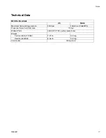
Страница 17: ...US Metric Maximum fluid working pressure 3000 psi 206 8 bar 20 68 MPa Dispense Valve Fluid Inlet Size 1 4 npt Wetted Parts 303 SST PTFE perfluoroelastomer Weight Cart manifold 17D763 7 27 lb 3 23 kg Remote 24W861 6 46 lb 2 93 kg Fluid Outlet 3 8 npsm m ...

Страница 18: ...erial or workmanship repairs will be made at a reasonable charge which charges may include the costs of parts labor and transportation THIS WARRANTY IS EXCLUSIVE AND IS IN LIEU OF ANY OTHER WARRANTIES EXPRESS OR IMPLIED INCLUDING BUT NOT LIMITED TO WARRANTY OF MERCHANTABILITY OR WARRANTY OF FITNESS FOR A PARTICULAR PURPOSE Graco s sole obligation and buyer s sole remedy for any breach of warranty ...

Отзывы: