Maintenance
3A9034B
17
Accelerator Calibration (Using Kit 25N880)
1. Turn power OFF. Engage Parking/Emergency
Brake.
2. Slowly raise hitch Coupler until LineDriver rests on
rear bumper.
3. Remove accelerator from LineDriver.
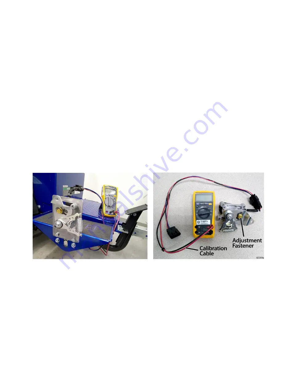
4. Connect calibration cable per illustration. Use a
Digital Multi-Meter to measure volts DC.
5. Mount accelerator to calibration plate and plate to
pedal. This makes it easier to torque fasteners.
6. Ensure nothing is on the operator’s seat so the Seat
Interlock Switch prevents wheel movement. Turn
power ON.
7. Loosen adjustment fastener and set neutral
position voltage to 2.45 ± .05 volts. Use calibration
plate to hold accelerator in this position. Torque
adjustment fastener to 90-100 in-lbs.
8. Rotate accelerator arm back and forth, then return
it to neutral position. Re-adjust voltage if
necessary. Turn power OFF.
9. Install accelerator onto LineDriver. When
connecting linkage, adjust tie rod end so no
pressure is needed to align parts. Otherwise the
LineDriver will creep.
10. LineDriver may creep forward or reverse when
turned on. As a precaution, jack unit up and use
jack stands to support it (two under the frame in the
rear and one under the Coupler).
11. Connect the LineDriver to a striper or grinder, sit on
the seat and turn on. If wheels do not turn (with no
pressure on speed pedals), calibration is complete.
Содержание LineDriver 25U670
Страница 15: ...Maintenance 3A9034B 15 Throttle Linkage Adjustment ...
Страница 28: ...Parts Drawing 28 3A9034B Parts Drawing Torque cable cap screws or nuts to 7 8 ft lbs 9 11 N m 1 ...
Страница 31: ...Parts Drawing 3A9034B 31 Parts Drawing Clamped parts must move freely after tightening 1 1 1 1 ...
Страница 34: ...Wiring Diagram Harness 25N661 34 3A9034B Wiring Diagram Harness 25N661 ...
Страница 35: ...Wiring Diagram 3A9034B 35 Wiring Diagram ...
Страница 36: ...Wiring Diagram Harness 25E406 36 3A9034B Wiring Diagram Harness 25E406 ...


