


Service
Service
Service the
the
the Bottom
Bottom
Bottom Piston
Piston
Piston Housing
Housing
Housing
Use this procedure to replace the seals in the lower
piston housing.
1.
With the isolation valve lying down, remove the
check valve assembly (238).
2.
Unscrew and remove the bottom housing of the
piston cap (216). The housing includes a spring
(215) and o-ring (230). Residual wash fluid may
appear.
3.
Pull out the piston assembly (211- 214 and
o-rings).
Note
Be careful not to scratch or drop the
piston (211) when extracting and
handling.
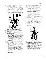
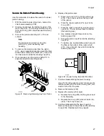
4.
To remove the retaining cap from the piston
(211), use an adjustable wrench around the flats
at the bottom of the piston shaft (211). Use a 3/8
inch hex wrench inside the retaining cap (214).
5.
Once loosened, turn the piston shaft (211) to
separate all piston assembly pieces.
Figure 31 Removing Retaining Cap from Piston
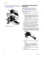
6.
Replace the piston seals:
a.
Place one U-cup (212) onto the piston cap
(216). The U-cup must face the top (shaft
of the piston).
b.
Place the spacer washer (213) next to the
U-cup (212).
c.
Place the other U-cup (212) onto the piston
cap (216). The U-cup must face the bottom
(the retaining cup).
d.
Use medium strength thread lock on the
retaining cap (214).
e.
Screw the piston cap (216) into the retaining
cap (214).
f.
To tighten, use an adjustable wrench around
the flats at the bottom of the piston shaft
(211). Use a 3/8 inch hex wrench inside the
retaining cap (214).
Figure 32 U-cups Facing Opposite Directions
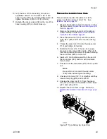
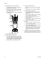
7.
Continue disassembling the lower housing:
Use a 15/16 inch socket or wrench to remove the
retainer (white) (202) from the housing (201). Be
careful not to strip the piece.
8.
Remove the retainer (202).
9.
Replace the retainer (202) seals:
a.
Replace the O-ring (208) into the groove next
to the threading.
b.
Replace the U-cup (203) where it sinks into
place. The U-cup faces out.
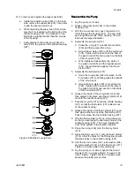
10. Continue disassembling the lower housing:
Remove the spacer U-cup (206) and the packing
U-cup (204). Residual paint may appear.
3A7370B
67
Содержание HydroShield WMBH00
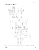
Страница 76: ...Repair Figure 42 Electrical Schematic for 26C716 Electrical Control equipped for gun flush box 76 3A7370B ...
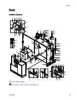
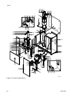
Страница 82: ...Parts Figure 46 Isolation Cabinet Interior 82 3A7370B ...
Страница 88: ...Parts 25N031 25N031 25N031 Pump Pump Pump Parts Parts Parts Figure 48 Pump 88 3A7370B ...


