
5
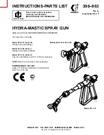
306-863
Installation
System Requirements
WARNING
The equipment must have a bleed-type master air
valve (pneumatic pumps only) and a pressure drain
valve. These accessories help reduce the risk of
serious injury from fluid injection, splashing in the
eyes or on the skin, or moving parts, when
adjusting or repairing the pump or gun.
1.
The bleed-type master air valve relieves air
trapped between this valve and the pneumatic
pump after the air regulator is shut off. Trapped air
can cause the pump to cycle unexpectedly.
2.
The pressure drain valve assists in relieving fluid
pressure in the displacement pump, hose and gun;
triggering the gun to relieve pressure may not be
sufficient.
3.
Strain the fluid you are spraying if it contains
particles which could clog the spray tip.
Grounding
WARNING
FIRE AND EXPLOSION HAZARD
To reduce the risk of static sparking,
ground the pump and all other equipment
used or located in the spray area. Also
read FIRE OR EXPLOSION HAZARD on
page 2.
1.
Check your local electrical code for detailed
grounding instructions for your area and type of
equipment.
2.
Follow the grounding instructions provided in your
pump or sprayer manual. The gun obtains ground-
ing through connection to a properly grounded fluid
hose and pump or sprayer.
Installation
1.
Connect a grounded fluid hose to the gun inlet.
2.
With no tip installed, start the pump/sprayer. Flush
it according to the instructions supplied with it.
Prime the system with the fluid you are using.
3.
Follow the Pressure Relief Procedure, page 2.
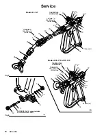
Fig 1
0957
1/2 npsm INLET
24
A
5
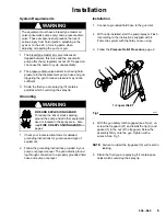
4.
With the gun safety latch engaged (see Fig 2), un-
screw the tip guard (21) and install the tip (A) and
gasket (5) in the nut of the tip guard. Screw the
assembly firmly onto the gun. Tighten with a
wrench. See Fig 1.
NOTE: Failure to install the tip gasket (5) will result in
leaking.
5.
Strain the fluid you are spraying if it contains par-
ticles which could clog the spray tip.