background image

3A9121A

EN

Instructions

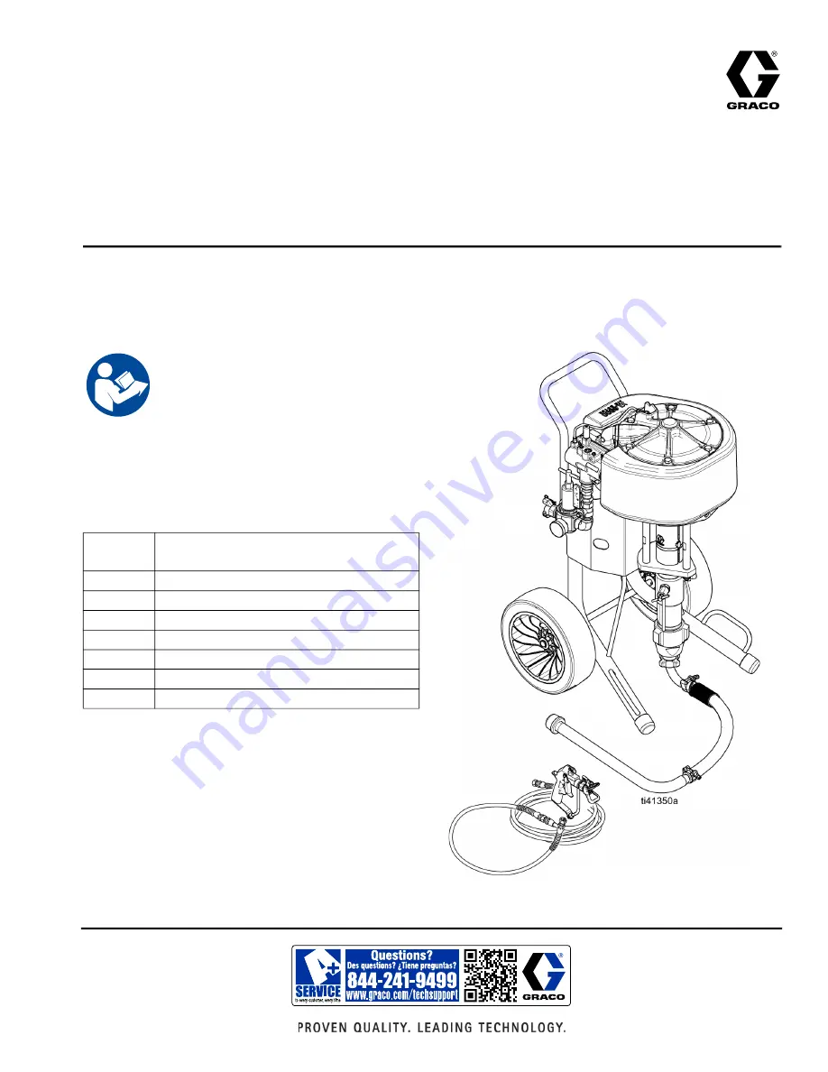
Contractor King

 Spray 

Packages and Pumps

High pressure spray packages for applying high performance coatings. For professional 

use only. 

See page for model information, including maximum 

working pressure and approvals.

Related Manuals

Important Safety Instructions

Read all warnings and instructions in this 

manual and related manuals before 

using the equipment. Save these 

instructions. 

Manual in 

English

Description

311254

Silver Gun and Silver HP Gun

3A9122

Lower Manual (pump)

333507

Hopper Kit

3A9126

Zinc Circulation Kit

3A9127

Air Filter Lubrication, Air Regulation Kits

3A9129

Lift Ring Kit

3A9128

Paint Filter Kit

Содержание Contractor King 19D624

Страница 1: ...ressure and approvals Related Manuals Important Safety Instructions Read all warnings and instructions in this manual and related manuals before using the equipment Save these instructions Manual in English Description 311254 Silver Gun and Silver HP Gun 3A9122 Lower Manual pump 333507 Hopper Kit 3A9126 Zinc Circulation Kit 3A9127 Air Filter Lubrication Air Regulation Kits 3A9129 Lift Ring Kit 3A9...

Страница 2: ...tion 18 Motor Lubrication 18 Run Motor Manually 20 Troubleshooting General 21 Repair 22 Remove Lower 22 Disconnect and Reconnect Lower 22 Remove Pump 23 Install Pump 24 Troubleshooting Air Motor 25 Air Motor Repair 27 Ice in Air Motor 27 Repair Air Valve 27 Replace Pilot Valve 29 Disassemble the Air Motor 29 Reassemble the Air Motor 30 Piston Seal Replacement 31 Parts 34 Contractor Kit Parts 34 Co...

Страница 3: ...er trigger 279022 Big 150 Silver HP 2 finger trigger 3 8 in x 150 ft 1 4 in x 6 ft 279031 Silver HP 4 finger trigger Ex II 2G Ex h IIA 230 C T2 Gb X Kit Gun Model Hose Whip Hose Maximum Working Pressure psi MPa bar Contractor King 45 1 19D624 Silver 2 finger trigger 273329 3 8 in x 50 ft 1 4 in x 6 ft 4500 31 MPa 310 bar 19D626 Silver 4 finger trigger 273346 3 8 in x 50 ft 1 4 in x 6 ft 4500 31 MP...

Страница 4: ...of debris including solvent rags and gasoline Do not plug or unplug power cords or turn power or light switches on or off when flammable fumes are present Use only grounded hoses Hold gun firmly to side of grounded pail when triggering into pail Do not use pail liners unless they are anti static or conductive Stop operation immediately if static sparking occurs or you feel a shock Do not use equip...

Страница 5: ...eplace worn or damaged parts immediately with genuine manufacturer s replacement parts only Do not alter or modify equipment Alterations or modifications may void agency approvals and create safety hazards Make sure all equipment is rated and approved for the environment in which you are using it Use equipment only for its intended purpose Call your distributor for information Route hoses and cabl...

Страница 6: ...auge F Packing Nut G Air Regulator Adjustment H Air Motor J Fluid Drain Purge Valve required K Fluid Filter sold separately L Grounding Wire M Pump N Suction Hose with Swivel and Tube P Pump Fluid Outlet PG Pump Guard R Manual Override Buttons S Spray Gun T De Ice Control bleed air U Hopper Kit sold separately W Fluid Hose X Filter and Water Separator Kit sold separately Y Regulator Air Filter Wat...

Страница 7: ... pressure exceeds the rated limit Air Filter and Water Separator X Remove harmful dirt from compressed air supply A minimum of 40 micron filter should be used if filtration is necessary Air Regulator Adjustment G Adjusts air pressure to the motor and fluid outlet pressure of pump Locate it close to the pump Read air pressure on air pressure gauge E Fluid Drain Purge Valve J Open valve to relieve p...

Страница 8: ...dboard which interrupts grounding continuity To maintain grounding continuity when flushing or relieving pressure hold metal part of the spray gun dispense valve firmly to the side of a grounded metal pail then trigger the gun valve Grounding Installation Tools Required Grounding wires and clamps for pails Two 5 gallon 19 liter metal pails 1 Verify the ground wire 244524 L is attached to the groun...

Страница 9: ...y conductive fluid hose W to pump outlet P and tighten 7 Attach electrically conductive fluid hose W to gun S and tighten Check that all pressure connections are tight 8 Attach an air compressor hose to the air inlet claw fitting A 9 Close the bleed type master air valve B Purge the air supply hose 10 Flush and prime before using See Flush page 12 and Prime page 15 To avoid tip over ensure cart is...

Страница 10: ...y against a grounded metal pail Trigger the gun until pressure is relieved NOTE If fluid does not flow from gun see Clearing a Clogged Tip page 11 5 Engage trigger lock This equipment stays pressurized until pressure is manually relieved To help prevent serious injury from pressurized fluid such as skin injection splashing fluid and moving parts follow the Pressure Relief Procedure when you stop s...

Страница 11: ...tip guard retaining nut or hose end coupling to relieve pressure gradually b Loosen nut or coupling completely c Clear hose or tip obstruction Clearing a Clogged Tip 1 Engage trigger lock 2 Rotate tip 180 so arrow on tip cylinder faces backward 3 Disengage trigger lock 4 Trigger gun into pail to remove clog 5 Engage trigger lock then rotate tip 180 back to spray position 6 If tip is still clogged ...

Страница 12: ...elief Procedure page 10 2 Remove tip and tip guard from gun 3 If desired remove fluid filter Reinstall filter cap after removing fluid filter 4 Connect the ground wire L and clamp to a true earth ground 5 Place suction tube in a compatible solvent NOTE Do not stretch hose tight Let it hang to assist fluid flow into the pump 6 Turn air regulator adjustment knob G counterclockwise until air pressure...

Страница 13: ...p will stop Once the material stops flowing release the trigger and engage the trigger lock NOTE When shutting down the unit for the day stop the pump with the rod buried in the pump d Close the bleed type master air valve 9 If flushing through drain purge valve a Place drain tube in a grounded waste pail Open fluid drain purge valve J slightly by rotating counterclockwise b Turn air regulator adj...

Страница 14: ...ump will stall f Stop the pump with the rod buried in the pump g Turn the air regulator adjustment knob G counterclockwise until air pressure gauge E reads zero h Close bleed type master air valve B 10 Perform Pressure Relief Procedure page 10 11 If equipped remove fluid filter and soak in solvent Replace filter cap ...

Страница 15: ... air regulator adjustment knob G counterclockwise until air pressure gauge E reads zero 5 Open bleed type master air valve B 6 Prime through drain valve if necessary NOTE Usually required for high viscosity materials a Place drain tube in a grounded waste pail Open drain purge valve J by slightly rotating counterclockwise NOTICE Do not prime pump through drain purge valve using two component mater...

Страница 16: ...d gun a Disengage gun trigger lock Hold the metal part of the gun against a grounded metal pail b Trigger gun slowly open air regulator adjustment knob G until pump beings to cycle and a steady stream comes from gun Trigger gun for 10 15 seconds c Engage trigger lock d The equipment is now ready to spray proceed to the Spray page 17 ...

Страница 17: ...a test pattern Read fluid manufacturer s recommendations Adjust pressure as necessary Shutdown Perform Prime page 15 Always flush the pump before the fluid dries on the displacement pump rod Perform the Flush procedure on page 12 Turn off and relieve air pressure in the air supply hose NOTICE Running the pump while dry will cause the pump to quickly accelerate to a high speed and cause dam age To ...

Страница 18: ...line filter Corrosion Protection Always flush the pump before the fluid dries on the displacement rod Never leave water or water based fluid in the pump overnight Motor Lubrication Graco does not require lubrication beyond the grease installed at the factory or through regular maintenance With good quality compressed air and normal ambient conditions However if any of the following criteria apply ...

Страница 19: ...thium based grease Remove and disassemble the air valve see Remove Pump page 23 Grease all visible moving parts especially detent and valve pistons Add Accessory Air Lubricator for Motor Lubrication To add a lubricator with kit 19D955 Add oil to line for whole motor lubrication Disconnect air line close to the motor and add 1 2 cc of SW30 oil NOTE Adding oil to the air motor will result in some oi...

Страница 20: ...ually operation the buttons 2 If a pilot valve is plugged a Press the button on the end where the motor stopped This will cause the motor to run another cycle b Press the button again to finish flushing 3 If a pilot valve is stuck in the open position or the pilot signal is leaking a Press the button on the opposite end from where the motor stopped and hold it in This will cause the motor to strok...

Страница 21: ...es closed or clogged Clear air line increase air supply Check that valves are open Fluid hose gun obstructed hose ID too small Clear hose or gun use hose with larger ID Air motor icing Open De Ice control Output low on down stroke Open or worn intake valve Clear or service intake valve High viscosity fluid Adjust intake spacers Output low on upstroke Open or worn piston valve or packings Clear pis...

Страница 22: ...12 Stop the pump at the bottom of its stroke 2 Perform Pressure Relief Procedure page 10 3 Turn off and relieve air pressure in air supply hose 4 Disconnect air hose 5 Disconnect fluid hose W Hold pump outlet fitting P with a wrench to keep it from loosening while you disconnect fluid hose NOTE Note the relative position of pump fluid outlet P to inlet of motor for easier reassembly alignment If m...

Страница 23: ... page 22 2 Use a flathead screwdriver to remove the pump guard PG 3 Remove rod coupling 4 If using a cart mounted unit tip the cart onto its back NOTE Lay rags onto the floor to catch TSL that may spill out of the packing nut 5 Loosen jam nut 6 Spin pump to remove ...

Страница 24: ...s back 2 Install pump by threading it into place Threads should be even with the top surface Jam nut tight to bottom of surface 3 Re install rod coupling CP and pump guard PG 4 Tighten jam nut 5 Refill packing nut with TSL Threads even with top surface Jam nut tight to bottom surface ...

Страница 25: ...art motor Air motor doesn t run and large volume of air blows through exhaust outlet on either stroke Main motor piston o ring 6 has failed or main valve See below Replace piston o ring 6 See Parts page 34 Air exhausts from rear outlet continuously when motor is stalled against fluid valve on one stroke or the other Shuttle valve cup 313 and plate 314 failure Replace shuttle valve cup 313 and plat...

Страница 26: ... or fitting Thaw any ice in pilot valve or replace valve D if it is not ice Air motor bounces does not fully complete its stroke at bottom change over Leaking top pilot valve or fitting Thaw any ice in pilot valve or replace valve 62 if it is not ice Air motor pauses at top change over Top pilot valve exhaust restricted by dirt or ice Swap pilot valve or clear exhaust port Air motor pauses at bott...

Страница 27: ...r content of the air Raise the compressed air temperature Warmer air going in helps the motor parts stay above freezing Compressed air especially at these volumes is warm when compressed Keep the air warm or stay near the compressor to reduce icing Use the bleed air to clear ice build up Repair Air Valve Replace Complete Air Valve 1 Stop the pump at the middle of its stroke Follow the Pressure Rel...

Страница 28: ...emove end cap o rings 317 5 Remove manual shuttle override buttons 319 from inside end caps 6 Remove manual shuttle override button o rings 318 7 Slide out the piston 304 Ramp 305 is adhered to the housing 301 and can be reused Reassemble the Air Valve 1 The piston 304 and u cup seals 306 come pre assembled Lubricate the u cup seals 306 on both ends of the piston 304 and install it in the housing ...

Страница 29: ...b 11 12 N m 5 Reconnect air line to the motor Disassemble the Air Motor 1 Follow steps in Prepare to Service Lower page 22 2 Disconnect pilot valve air lines 37 38 from the air valve 30 3 Remove six screws 27 and remove the manifold and valve 30 and two gaskets 24 Inspect foam for damage 4 Use a 3 4 in or 19 mm socket wrench to remove the bolts 31 5 Remove the top cover 22 Remove the o ring 6 6 Re...

Страница 30: ...on the bottom cover 1 2 Lubricate and install new u cup seal with flange 4 with the lips facing up in the bottom cover 1 from the bottom The seal will snap into place 3 Install o ring 6 in the bottom cover 1 Install retaining clip 5 Snap in the new bumper 9 4 Lubricate the inside of the cylinder 14 Lower the cylinder onto the bottom cover 1 5 Lubricate and install the o ring 13 around the piston 1...

Страница 31: ...askets 24 and screws 27 halfway onto manifold 25 10 Install bolts 31 halfway onto cover 1 11 Torque screws 27 to 120 in lb 13 6 N m 12 Torque cover bolts 31 evenly in a criss cross pattern to 40 ft lb 54 2 13 6 N m 13 Reconnect the pilot valve air lines 37 to air valve 30 and poppet valves 62 Piston Seal Replacement Removal Refer to the illustration on the following page for the instructions below...

Страница 32: ... top two 27 screws loosen lower two 27 screws to valve assembly 30 out of the way Retain top gasket 24 7 Remove six bolts 31 on top of motor cover 22 then remove cover 8 Slide piston rod 7 up to push piston 10 out the top of the motor 9 Remove piston seal 13 ...

Страница 33: ...14 4 Push piston rod 7 up Guide piston seal 13 into motor cavity then push piston seal down and into place with the piston 5 Replace motor cover 22 6 Re install top gasket 24 and screws 27 halfway onto manifold 25 7 Install bolts 31 halfway onto cover 1 8 Torque screws 27 to 120 in lb 13 6 N m 9 Torque cover bolts 31 evenly in a criss cross pattern to 40 ft lb 54 2 13 6 N m 10 Reconnect the pilot ...

Страница 34: ...Parts 34 3A9121A Parts Contractor King Parts Ref Torque 50 60 ft lb 68 81 N m 75 80 ft lb 100 110 N m 17 23 ft lb 23 31 N m 75 85 in lb 9 10 N m 2 8 9 11 ...

Страница 35: ...ontractor King 1 13 129334 SCREW hex serrated 1 4 20x1 50 4 15 131327 BOLT flange hd serrated 1 4 2 16 19D628 ROD tie Contractor King 3 17 18F695 ADAPTER mount pump 1 18 108851 WASHER plain 2 19 101712 NUT lock 3 20 LOWER Contractor King 1 19D951 180 cc 19D952 220 cc 19D954 290 cc 21 15M914 NUT jam 1 22 244819 COUPLING assembly 1 23 197340 COVER coupler 1 24 244820 CLIP hairpin w lanyard 1 25 19B9...

Страница 36: ...Parts 36 3A9121A XL6500 Air Motor Parts Ref Torque 33 3 ft lb 45 4 N m 40 3 ft lb 61 7 N m 80 5 in lb 108 7 N m 12 3 in lb 16 4 N m 80 5 in lb 108 7 N m 7 9 13 15 18 ...

Страница 37: ... 27 18D584 SCREW cap sch 10 28 295447 PIN dowel 1 29 17R950 GASKET valve 1 30 17V344 VALVE air XL motor includes 29 1 31 119050 BOLT cap hex head 6 32 17S075 FOAM temp barrier poppet 1 33 17M851 GASKET poppet housing 2 34 17V571 KIT poppet housing includes 33 34 35 36 67 2 35 17S929 ISOLATOR poppet housing 2 36 17V969 SCREW shcs m5 X 12 6 37 17R463 TUBE pilot air top XL6500 1 38 19D631 TUBE pilot ...

Страница 38: ...ve Parts 17V344 Standard Valve ti37411a 301 314 304 305 307 308 309 310 306 306 319 319 303 317 317 321 323 322 302 302 15 315 325 329 320 316 316 313 318 320 318 1 1 2 1 Apply high quality lithium grease 2 Blue thread sealant ...

Страница 39: ...IR XL lapped 1 314 PLATE low noise XL lapped 1 PLATE valve air XL lapped 1 315 SCREW flat head M5 thread form 2 316 17N617 CAP valve air XL machined 2 317 104010 PACKING o ring 2 318 154741 PACKING o ring 2 319 17A511 PIN reset XL air valve 2 320 557832 RING retaining 2 321 PLUG valve molded 1 322 104130 PACKING o ring 1 323 RING retaining 1 325 117026 SCREW shcs M5 X 12 2 326 LUBRICANT grease 1 3...

Страница 40: ... consumption scfm or m3 min at a specific fluid flow gpm lpm and air pressure psi MPa bar use the following instructions and pump data charts 1 Locate desired flow along the bottom of the chart 2 Follow the vertical line up to the intersection with the selected fluid outlet pressure curve Follow right to scale to read air flow consumption 45 1 Ref Pressure A 100 psi 0 7 MPa 7 bar B 70 psi 480 MPa ...

Страница 41: ...345 4000 276 3000 207 2000 138 1000 69 0 17 34 37 49 51 64 66 0 5 1 5 2 5 3 5 4 5 300 8 5 1 0 2 0 3 0 4 0 5 0 A B C A B C Cycles Per Minute cpm Fluid Pressure psi bar Air Flow scfm m3 min Fluid Flow gpm lpm 5000 345 4000 276 3000 207 2000 138 1000 69 8000 556 0 20 21 38 40 67 69 7000 482 6000 414 0 5 1 5 2 5 3 5 1 0 2 0 3 0 4 0 250 7 1 200 5 6 150 4 2 100 2 8 50 1 4 0 300 8 5 A B C A B C ...

Страница 42: ... psi 0 48 MPa 4 8 bar at 15 cpm per ISO9614 2 106 dBA Sound Pressure Tested at 3 28 ft 1 meter from equipment per ISO9614 2 97 dBA Wetted Parts Carbon steel ally steel 304 440 and 17 4 PH grades of stainless steel zinc and nickel plating ductile iron tungsten carbide PTFE leather Fluid Inlet Size 1 1 4 npt m Fluid Outlet Size Number of Outlets 1 1 2 in npt f Maximum Air Operating Pressure 100 psi ...

Страница 43: ...ry 5 years or less based on use End of Life Disposal If the sprayer is in a condition that it can no longer operate the sprayer should be taken out of service and dismantled Individual parts should be sorted by material and disposed of properly Key construction materials can be found in the Materials of Construction Section Graco Date Code Serial Code Month Year 2nd and 3rd characters Series 4th c...

Страница 44: ...California Proposition 65 44 3A9121A California Proposition 65 CALIFORNIA RESIDENTS WARNING Cancer and reproductive harm www P65warnings ca gov ...

Страница 45: ...INCLUDING BUT NOT LIMITED TO WARRANTY OF MERCHANTABILITY OR WARRANTY OF FITNESS FOR A PARTICULAR PURPOSE Graco s sole obligation and buyer s sole remedy for any breach of warranty shall be as set forth above The buyer agrees that no other remedy including but not limited to incidental or consequential damages for lost profits lost sales injury to person or property or any other incidental or conse...

Страница 46: ...changes at any time without notice Original instructions This manual contains English MM 3A9121 Graco Headquarters Minneapolis International Offices Belgium China Japan Korea GRACO INC AND SUBSIDIARIES P O BOX 1441 MINNEAPOLIS MN 55440 1441 USA Copyright 2022 Graco Inc All Graco manufacturing locations are registered to ISO 9001 www graco com Revision A April 2022 ...

Отзывы: