Startup
Startup
To prevent serious injury, only operate Reactor
with all covers and shrouds in place.
NOTICE
Proper system setup, startup, and shutdown
procedures are critical to electrical equipment
reliability. The following procedures ensure steady
voltage. Failure to follow these procedures will
cause voltage fluctuations that can damage
electrical equipment and void the warranty.
1. Check generator fuel level.
Running out of fuel will cause voltage fluctuations
that can damage electrical equipment.
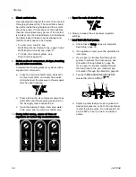
2. Check coolant levels.
Inspect the level of coolant inside the engine
coolant expansion bottle (EB) and heat
exchanger coolant expansion bottle (HB).
COLD
HOT
COLD
HOT
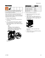
3. Check fluid inlet screens.
Before daily startup, ensure that the
fluid inlet screens are clean. See
Flush Inlet Strainer Screen, page 67
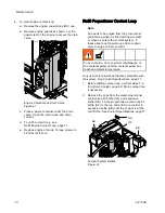
4. Check ISO lubrication reservoir.
Check level and condition of ISO lube daily. See
Pump Lubrication System, page 68.
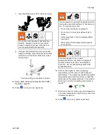
5. Confirm main power switch is OFF before starting
generator.
6. Start the generator.
Press start button
twice on the engine
control module. The controller will automatically
sequence glow plug warming and crank
operations. Allow engine to reach full operating
speed.
Note
Engine will not start if main power switch
is in the on position.
Note
If the engine control module screen
does not light up after the start button is
pressed, see the system repair manual.
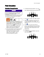
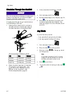
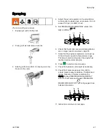
7. Turn main power switch ON.
When the system is powered up by turning the
main power switch (MP) to the ON position, the
splash screen will display until communication
and initialization is complete.
3A1705E
55
Содержание 259079
Страница 34: ...Setup A5 A1 A2 AS AN A3 AT A3 A4 A2 A6 A4 34 3A1705E...
Страница 45: ...Advanced Display Module ADM Operation Setup Screens Navigation Diagram Figure 35 3A1705E 45...
Страница 49: ...Advanced Display Module ADM Operation Run Screens Navigation Diagram Figure 36 3A1705E 49...
Страница 93: ...Dimensions Dimensions Top View Figure 43 Side View Figure 44 3A1705E 93...
Страница 95: ...Dimensions Pallet Mounting Dimensions Figure 48 3A1705E 95...
Страница 97: ...Notes Notes 3A1705E 97...

