background image

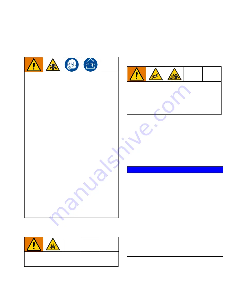
Important Isocyanate (ISO) Information

313566J

5

Important Isocyanate (ISO) Information

Isocyanate Conditions

Material Self-ignition


Keep Components A and B 
Separate

Moisture Sensitivity of 
Isocyanates

Exposure to moisture (such as humidity) will cause ISO 
to partially cure, forming small, hard, abrasive crystal 
that become suspended in the fluid. Eventually a film will
form on the surface and the ISO will begin to gel, 
increasing in viscosity.

NOTE:

 The amount of film formation and rate of crystal-

lization varies depending on the blend of ISO, the 
humidity, and the temperature.

Spraying or dispensing fluids that contain isocyanates
creates potentially harmful mists, vapors, and
atomized particulates.

Read and understand the fluid manufacturer’s 
warnings and Safety Data Sheet (SDS) to know 
specific hazards and precautions related to isocy-
anates.

Use of isocyanates involves potentially hazardous 
procedures. Do not spray with this equipment 
unless you are trained, qualified, and have read 
and understood the information in this manual and 
in the fluid manufacturer’s application instructions 
and SDS.

Use of incorrectly maintained or mis-adjusted 
equipment may result in improperly cured mate-
rial. Equipment must be carefully maintained and 
adjusted according to instructions in the manual.

To prevent inhalation of isocyanate mists, vapors, 
and atomized particulates, everyone in the work 
area must wear appropriate respiratory protection. 
Always wear a properly fitting respirator, which 
may include a supplied-air respirator. Ventilate the 
work area according to instructions in the fluid 
manufacturer’s SDS.

Avoid all skin contact with isocyanates. Everyone 
in the work area must wear chemically imperme-
able gloves, protective clothing and foot coverings 
as recommended by the fluid manufacturer and 
local regulatory authority. Follow all fluid manufac-
turer recommendations, including those regarding 
handling of contaminated clothing. After spraying, 
wash hands and face before eating or drinking.

Some materials may become self-igniting if applied 
too thick. Read material manufacturer’s warnings and 
material Safety Data Sheet (SDS).

Cross-contamination can result in cured material in 
fluid lines which could cause serious injury or damage 
equipment. To prevent cross-contamination:

Never interchange component A and component 
B wetted parts. 

Never use solvent on one side if it has been con-
taminated from the other side.

NOTICE

Partially cured ISO will reduce performance and the life 
of all wetted parts.

• Always use a sealed container with a desiccant 

dryer in the vent, or a nitrogen atmosphere. 

Never 

store ISO in an open container.

• Keep the ISO pump wet cup or reservoir (if 

installed) filled with appropriate lubricant. The 
lubricant creates a barrier between the ISO and 
the atmosphere.

• Use only moisture-proof hoses compatible with 

ISO.

• Never use reclaimed solvents, which may contain 

moisture. Always keep solvent containers closed 
when not in use.

• Always lubricate threaded parts with an 

appropriate lubricant when reassembling.

Содержание 1093

Страница 1: ...ressure Metal Sleeves 1200 psi 8 MPa 83 bar Maximum Mate rial Inlet Pressure Plastic Sleeves 400 psi 2 8 MPa 28 bar Maximum Material Inlet Pressure 100 psi 0 7 MPa 7 bar Maximum Air Working Pressure 110 F 43 C Maximum Ambient Temperature 150 F 65 C Maximum Operating Temperature Important Safety Instructions Read all warnings and instructions in this manual Save these instructions ...

Страница 2: ...bly 23 Assembly 24 Model 1093 Recommended Spare Parts 27 General Guidelines for O Rings and U Cup Seals 28 O Ring Guidelines 28 U Cup Seal Guidelines 28 Technical Data 29 Motor Specifications 29 Graco Standard Warranty 30 Graco Information 30 Related Manuals 1093 Valve Models Part Description 3A0261 1053 1093 Control Box 1093 Valves Part No Configuration Description A2A05401 1093 10A 4RS1 500 V 2 ...

Страница 3: ...ly Replace worn or damaged parts immediately TOXIC FLUID OR FUMES HAZARD Toxic fluids or fumes can cause serious injury or death if splashed in the eyes or on skin inhaled or swallowed Read Safety Data Sheets SDSs for handling instructions and to know the specific hazards of the fluids you are using including the effects of long term exposure When spraying servicing equipment or when in the work a...

Страница 4: ...re compatible with equipment wetted parts See Technical Specifica tions in all equipment manuals Read fluid and solvent manufacturer s warnings For complete information about your material request Safety Data Sheets SDSs from distributor or retailer Do not leave the work area while equipment is energized or under pressure Turn off all equipment and follow the Pressure Relief Procedure when equipme...

Страница 5: ... respiratory protection Always wear a properly fitting respirator which may include a supplied air respirator Ventilate the work area according to instructions in the fluid manufacturer s SDS Avoid all skin contact with isocyanates Everyone in the work area must wear chemically imperme able gloves protective clothing and foot coverings as recommended by the fluid manufacturer and local regulatory ...

Страница 6: ...es used in your equipment requires special attention to avoid equipment damage and downtime When changing materials flush the equipment multiple times to ensure it is thoroughly clean Always clean the fluid inlet strainers after flushing Check with your material manufacturer for chemical compatibility When changing between epoxies and urethanes or polyureas disassemble and clean all fluid componen...

Страница 7: ...r and dispense device accurately meters liquid and semi paste materials The machine is designed for applications that require very small and precisely dispensed beads and or dots of material at a wide range of material inlet pressures The ratio of the flow rate stroke length to pump shaft area provides the adjustable pressure intensification needed to move the separate liquids through the needle w...

Страница 8: ...Component Identification 8 313566J Component Identification Typical System Configurations FIG 1 CONTROL POWER 9 40 0 8 46 0 5 0 4 Valve Controls System shown with optional controls ...

Страница 9: ...ND WEARING SAFETY GLASSES WARNING F 20 0 psi 0 20 oz Cartridge Feed with Mounting Post 5 Gallon Pail Cover with Diaphragm Pump 1 Gallon Ram and Pump 5 Gallon Pail Cover with Diaphragm Pump and Agitator 5 Gallon Ram and 11 1 Transfer Pump 5 Gallon Pail Cover with Diaphragm Pump 5 Gallon Pail Cover with 5 1 Transfer Pump ...

Страница 10: ...ntinued FIG 3 R 0 12 8 4 psi 30 22 19 15 26 R 0 12 8 4 psi 30 22 19 15 26 5 Gallon Tank with Diaphragm Pump and Stand 5 Gallon Tank with 5 1 Pump and Stand 10 Gallon Tank with Diaphragm Pump Agitator Vacuum and Stand 10 Gallon Tank with 5 1 Pump Agitator Vacuum and Stand ...

Страница 11: ...Component Identification 313566J 11 Model 1093 Main Component Illustration FIG 4 ...

Страница 12: ... The inside diameter of the standard motor cou pler is 25 Air Lines Install the pneumatic supply lines for spool shifting between the fill and dispense cycles Minimum air pressure required is 70 psi 4 8 bar Maximum air pressure is 100 psi 6 9 bar Pneumatic supply lines of 16 inch ID X 25 inch OD Spool Position Sensors The spool sensors are mag netic reed switches that must be connected to an elect...

Страница 13: ... Diagram If using a non Graco motor with the dispense valve use the following diagram to install the non Graco motor onto the valve See Motor Specifications on page 29 FIG 6 2 22 2 22 2 039 0 182 2 039 0 182 Ø 0 251 STANDARD 4X 10 32 Thru 1 515Ø X 0 062 DP ...

Страница 14: ...ring chambers by a pressurized feed system The outlet port is blocked The metering rod is retracted to a precise position determining the volume of each material Step 2 Shift The balanced spool shifts to the dispense position The material path to the needle is opened The material feed inlet port is blocked The metering rod remains in the retracted position Step 3 Dispense The metering rod extends ...

Страница 15: ...ir free material is visible Output Verification Output verification is a simple procedure where individual samples of material are collected weighed and compared for desired output We recommend that you perform output verification at least once a day and if the machine is used in production for more than one shift then once a shift 1 Position a clean container under the valve outlet 2 Set the stro...

Страница 16: ...s air to the metering valve 7 Close the incoming air shut off bleed valve that supplies the feed system See your feed system manual for the proper pressure relief procedure Shutdown 1 Perform the Pressure Relief Procedure 2 Inspect the metering rod for material buildup Clean as necessary 3 Lubricate the metering rod with compatible lubricant such as mesamoll or silicone oil 4 Remove the needle ada...

Страница 17: ... refill as necessary Ensure the material reservoirs are properly vented Air Dryer Check the condition of the desiccant air dryer Replace as necessary Metering Rod Port oil cup Lubricate with compatible lubricant such as mesamoll or silicone oil Exterior Check and clean the exterior of the valve Spool Valve Port wet cups Fill with compatible lubricant such as mesamoll or sili cone oil ...

Страница 18: ...vel in reservoirs Fill material reservoirs and prime the machine Air in material tank Fill reservoir and prime machine Material leaks past spool valve Spool valve worn or damaged Replace the spool valve The 1093 valve will not cycle Cycle detection sensors not working Check connections or replace as needed The 1093 valve cycles slowly Oil cup wet cups are not supplied with lubrication Add lubricat...

Страница 19: ...3566J 19 Parts 1093 Valve The motor is not included with the valve 101 102 103 104 105 106 107 126 124 131 127 125 124 129 110 111 112 113 136 128 108 109 133 123 122 121 120 119 118 116 115 114 135 137 138 142 ...

Страница 20: ... SCREW shc 4 133 617559 SCREW cap 4 135 A2010029 NEEDLE 1092 adptr asy 1 136 123537 BUTTON snap on green 1 137 123538 BUTTON snap on yellow 1 138 84 0130 22 11 CRUSH LABEL 2 139 84 0130 25 11 GROUND LABEL 1 140 96 0005 2 99 WASHER 2 141 96 0124 99 NUT 2 142 81 9997 M 11 TERMINAL 1 149 070311 ADHESIVE 1 Ref No Description RS 500 RS 625 RS 750 TT 500 TT 625 TT 750 Qty A2A05401 A2A05402 A2A05403 A2A0...

Страница 21: ...1 210 514210 SCREW fhsc 1 211 96 0328 2 98 SCREW shc 4 212 01 2990 97 HOUSING lead screw 1 213 130858 SCREW bhsc 2 214 96 0209 99 RING ret ext 1 215 84 0129 11 BALL 1 216 01 2993 25 NUT lead screw drive 1 217 01 2994 1 25 SCREW lead screw drive 1093 1 219 01 2991 1 97 COUPLER lead screw pd44 1 220 128410 SCREW shc 2 221 01 2992 97 RETAINER bearing lead screw pd3 1 222 01 2890 97 PLATE mtg stpr pd4...

Страница 22: ...3 Ref Part Description Qty 301 A2000166 BLOCK 1092 inlet ss 1 302 A2000290 GASKET 1092 1 303 A2000205 BLOCK 1092 1 304 B4000016 SCREW shc ss 2 305 J1000002 PIN roll ss 2 306 B4000010 SCREW sch ss 316 4 307 94 0300 1 98A FITTING elbow 1 308 E4000016 ADAPTER 1 309 95 0904 00 O RING fkm 1 ...

Страница 23: ...be sure to keep the spools and sleeves matched 7 Remove the needle block 303 from the inlet block 301 8 Remove the inlet block 301 from the valve body 107 9 Remove the o rings 119 from the valve body 107 10 Remove the spool wet seal retainers 114 on the left and right of the valve body 107 11 Remove the valve body 107 from the oil cup retainer 124 by removing the screws 126 12 Remove the rod sleev...

Страница 24: ...s before proceeding NOTE Use caution when installing a new u cup and Posipak seals so they are not pinched or torn To do this make sure the seals are lubricated and the lips of the seal are tucked inward before uniformly pushing them into position 1 Install four lubricated o rings 118 onto the spool sleeve assembly 116 Lubricate the spool rod and the outside of the spool rod sleeve along with the ...

Страница 25: ... 124 14 Pull the metering rod 102 away from the assem bled unit and slide it into the key slot in the metering rod connection block 207 15 Guide the metering rod 102 and assembled unit into the rod sleeve 106 16 Carefully place the seal cup 103 Posipak seal 104 and oil cup retainer 124 down against the main body and secure with screws 126 NOTE If the motor and motor coupling assembly 219 was disas...

Страница 26: ...Motor Coupling illustration on page 21 for more informa tion 2 Assemble the lead screw nut 216 with the bearing 215 and e ring 214 3 Thread the lead screw 217 into the lead screw nut assembly 216 until the lead screw is flush with the top of the nut 4 Slide the lead screw and nut assembly into the housing 212 5 Slide the bearing retaining sleeve 221 on to the lead screw assembly Take care to line ...

Страница 27: ...4 NEEDLE 16 GUAGE x 75 Pack of 4 A9010010 4 NEEDLE 17 GUAGE x 75 Pack of 4 A9010011 4 NEEDLE 18 GUAGE x 75 Pack of 4 A9010012 4 NEEDLE 19 GUAGE x 75 Pack of 4 A9010013 4 NEEDLE 20 GUAGE x 75 Pack of 4 A9010014 4 NEEDLE 22 GUAGE x 75 Pack of 4 A9010020 4 Luer Lock Hub Replacement Needles for Single Needle Block Models Needle length shown is length projecting from LL hub Other lengths available Desc...

Страница 28: ...ching the o ring too much as it may not return to the proper size Do not use any sharp tools or objects to install o rings U Cup Seal Guidelines Always replace u cup seals with new u cup seals identical in size durometer hardness type and material of construction Always be alert to the loca tion and size of each u cup seal and be careful not to mix them Similar sizes may be used in various locatio...

Страница 29: ...ressure 2000 psi 14 MPa 138 bar Maximum Air Working Pressure 100 psi 0 7 MPa 7 bar Minimum Air Working Pressure 70 psi 480 kPa 4 8 bar Maximum Material Inlet Pressure Metal Sleeves 1200 psi 8 MPa 83 bar Plastic Sleeves 400 psi 2 8 MPa 28 bar Supplied Air Requirements 1 to 3 cfm at 80 psi to 100 psi Shot Size Range depending on metering rods selected 0 193 cc to 14 479 cc Maximum Cycle Rate applica...

Страница 30: ...e at a reasonable charge which charges may include the costs of parts labor and transportation THIS WARRANTY IS EXCLUSIVE AND IS IN LIEU OF ANY OTHER WARRANTIES EXPRESS OR IMPLIED INCLUDING BUT NOT LIMITED TO WARRANTY OF MERCHANTABILITY OR WARRANTY OF FITNESS FOR A PARTICULAR PURPOSE Graco s sole obligation and buyer s sole remedy for any breach of warranty shall be as set forth above The buyer ag...

Отзывы: