Mounting
English, Revision 01, Date: 14.04.2009
6
3
Mounting
3.1
Casing
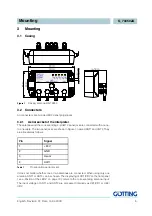
Figure 1
Casing antenna HG 73350
3.2
Connecters
All connecters are A-coded M12 panel plugs/jacks.
3.2.1
Aerial socket of the interpreter
The antennas and the corresponding 4-pin M12 panel jack are connected with an one-
to-one cable. The two panel jacks are shown in Figure 1, named ANT1 and ANT2. They
are allocated as follows:
It does not matter whether one or two antennas are connected. When using only one
antenna, ANT1 or ANT2 can be chosen. The displaying of CD1/CD2 on the front panel
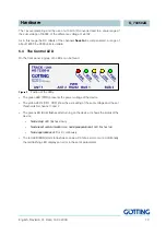
( see „Postion of the LEDs“ on page 10.) refers to the corresponding antenna input.
The input voltage of ANT1 and ANT2 are processed internally as US1/UD1 or US2/
UD2.
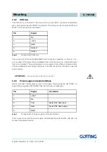
Pin
Signal
1
+24 V
2
GND
3
Usum
4
Udiff
Table 1
Pin allocation aerial socket
d
rillhole for mounting


