Identification Systems
English, Revision 03, Date: 07.02.2012
7
1.4.3
Signals and Timing
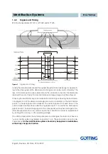
With the transponders G 71310, G 71320 and G 71325.
Figure 3
Signals and Timing
Initially the data are insecure and the signal strength is still small (range II). Approach-
ing further the signals of the data become stronger and can be read completely. The
loss of the interception area is detected via the controller in that the thresholds are
reached (3 and 4). Finally the internal interception range (range I) will be achieved.
Crossing the field border at point 4 releases the center signal. Passing the next detec-
tion ranges (5 to 8) the data are read again and will be indicated. At the field border,
point 8, no center signal will be released. The center signal will not even be set if the
vehicle stops and drives back after having passed point 1 to 4 within the interception
gap (4 and 5). The positioning signal for this transponder will only be send again if an-
other transponder with a new code is read in the meantime or a reset is implemented
by turning-off or turning- on the operating voltage.
If a vehicle stops before the central pulse ends and changes the direction of travel, a
“wrong“ central pulse is generated on position 1 or 4. These positions can not be de-
fined exactly.
So the identification system should only be applied in installations
without any change in direction.


