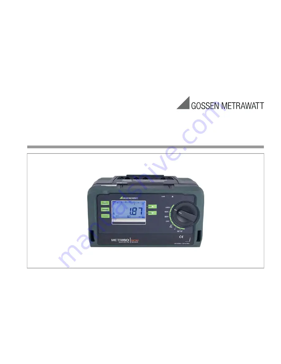
METR
ISO
INTRO
,
BASE
TECH
Insulation, Low Resistance and Voltage Measurement Instrument
3-349-812-03
4/8.19
Operating Instructions
www.
GlobalTestSupply
.com
Find Quality Products Online at:
[email protected]
Страница 1: ...SO INTRO BASE TECH Insulation Low Resistance and Voltage Measurement Instrument 3 349 812 03 4 8 19 Operating Instructions www GlobalTestSupply com Find Quality Products Online at sales GlobalTestSupply com ...
Страница 2: ...umber M550N M550O M550P Measurements RINS U 1000 V RINS U 250 500 V RINS U 50 100 V R 10 Ω 10 kΩ RLO 0 17 Ω 10 Ω U 0 1000 V U 0 500 V Display Functions Backlit display Limit value LED green red for Additional acoustic signal limit value per VDE 0100 RINS RLO RINS RLO RINS RLO LED for dangerous contact voltage when switched off LCD symbol for external voltage Battery level display Special Functions...
Страница 3: ...ielded plug in connector cable Battery Holder Battery Compartment Lid Battery Holder Contacts Battery Contact Spring User Interface Compartment COM COM SHIELD Shielded Cable Test Resistor Test Resistor Measuring Test Probe with Control Keys 1 10 MΩ Connector with Shielded Cable Option KS C Z541F G500 G100 G500 G1000 Connections GUARD not METRISO INTRO www GlobalTestSupply com Find Quality Products...
Страница 4: ...RMS AC DC Rlo 10 MAN DATA STORE ZERO G ISO 2500V 1000 V T k 100 k 1G 10 k 1M 10 G 0 1000 V 1200 G 100 M 10 M Green LED limit value adhered to SETUP parameter selection V voltage type selection Rlo polarity reversal Scroll up SETUP parameter selection V voltage type selection Rlo polarity reversal Test Measuring voltage with device switched on for Riso Rins menu from standby state measurement R RLO...
Страница 5: ...current type 8 ISO xxxV Insulation resistance measurement selected test voltage 9 Ω V Unit of measure 10 ZERO Cable compensation for low resistance measurement is active see rLEAd parameter on page 11 11 DATA Blinks during measurement Static measured value is stable 12 Warning regarding dangerous voltage U 50 V AC DC 13 Acoustic signal beeper active for exceeded limit values see bEEP parameter on ...
Страница 6: ...nt with Automatic Polarity Reversal AUTO Function 21 8 2 Measurement with Manual Polarity Reversal MAN Function 22 8 3 Taking Measurement Cables and Extension Cables into Account up to 10 Ohm ZERO Function Roffset 23 9 Test Resistor for Insulation Measurement for Checking the Insulation Measuring Instrument 23 10 Characteristic Values 24 11 List of Abbreviations and their Meanings 28 12 Maintenanc...
Страница 7: ... Insulation resistance measuring instruments Part 4 Instruments for the measurement of resistance at earthing conductors protective conductors and bond ing conductors Part 10 Combined measuring equipment for testing measuring or monitoring protective measures As well as requirements per VDE 0701 0702 Repair modification and inspection of electrical appliances The test instrument is especially well...
Страница 8: ...horized service per sonnel to ensure the safe and correct operation of the equipment and to keep the warranty valid Even original spare parts may be installed only by authorized ser vice personnel In case the equipment was opened by unauthorized personnel no warranty regarding personal safety measurement accuracy conformity with applicable safety measures or any consequential damage is granted by ...
Страница 9: ...These can only be recharged externally We recommend rechargeable NiMH batteries Always replace batteries in complete sets Dispose of batteries in an environmentally sound fashion Ð Loosen both slotted screws for the battery compartment lid on the back and remove the lid Ð Remove the battery holder and insert eight 1 5 V size AA bat teries with correct polarity in accordance with the symbols Attent...
Страница 10: ...ameters with the scroll keys and acknowledge by pressing the ENTER key The desired information is displayed in the scroll mode moving letters 3 3 1 Paths to the Various Parameters info SETUP bAtt uers ion 1nFo SET Query Parameter rlead APoFF blight bEEP A d iSP 0 d iSP START ENTER Acknowledge START ENTER Set Parameter Main Menus ESC stby OFF START ENTER ESC stby OFF www GlobalTestSupply com Find Q...
Страница 11: ...he display The measurement results i e the resistance of the two measure ment cables are subtracted from future low resistance measure ments as an offset value and ZERO appears in the footer After selecting the CLEAr parameter and acknowledging by press ing the ENTER key you re provided with the opportunity of per forming future measurements without using the offset If this is the case ZERO is no ...
Страница 12: ...ion after xx seconds after the last time the rotary switch is actuated can be selected in order to extend the battery service life As soon as a new measur ing function is selected or started illumination is reactivated When set to oFF illumination is permanently deactivated 1nFo SET rlead bligt 15 30 45 90 s off 15 seconds default setting bEEP Acoustic Indication of Exceeded Limit Values This para...
Страница 13: ...lt Settings Previously entered changes can be undone and default settings can be restored This may be advisable under the following cir cumstances After the occurrence of software or hardware errors If you are under the impression that the instrument does not work correctly Ð Disconnect the device from the measuring circuit Ð Briefly remove the batteries see also section 3 2 Ð Press and hold the k...
Страница 14: ...ted by pressing the stby OFF key The instrument can be switched off manually by turning the rotary switch to the OFF position Optical Indicators 1 Prerequisite The LiLEd parameter is set to on see page 13 2 Function testing should be executed regularly see following section on testing LEDs COM SHIELD KS C Z541F LED Status Function Cause Limit value indication 1 Measured insulation resistance does ...
Страница 15: ... Signal when RLO 2 Ω Continuity test Insulation Measurement Signal when RINS limit value 4 2 Measured Value Display The following appear at the LCD panel Measured value in digital format Measured value in analog format as bar graph or pointer Unit of measure Measured values for automatic measuring sequences are retained at the display as digital values until the next measure ment sequence is start...
Страница 16: ...sulation resistance measurement are included in section 14 1 Insulation resistance can only be measured at voltage free objects If mains voltage or external voltage is applied to the measurement inputs measurement cannot be started This is indicated by the high voltage symbol which appears at the display 5 2 Performing the Measurement Note Condensation must be ruled out when performing measure men...
Страница 17: ...ntinuous measurement is ended by briefly pressing the ESC key In either case the measured value is retained at the 7 segment display When discharging begins the unit of measure for the bar graph changes from Ω to V The length of the bar graph is contin uously reduced as voltage at the device under test drops Special Case Capacitive Devices Under Test Caution If measurement is performed at a capaci...
Страница 18: ...t cables to the and COM jacks Ð Contact the measuring point with both test probes The measured value is displayed directly without pressing the START key in analog format at the bar graph and in digital format at the 7 segment display Ð After completing the measurement switch the instrument off by turning the rotary switch to the OFF position The ESC START and CONTIN keys are disabled in this case...
Страница 19: ...not be started This is indicated by the high voltage symbol which appears at the display Ð Select measuring function kΩ or Ω with the rotary switch Ð Start an individual measurement by briefly pressing the START key or initiate continuous measurement by briefly pressing the CONTIN key DATA blinks at the display until the measured value has settled in kΩ COM Rx Rx 0V DATA 20 4 0 1000 START ENTER ww...
Страница 20: ...current values Connection Note Low value resistance can only be measured at voltage free objects Ð Connect the device under test to the and COM jacks Ð Select the Rlo measuring function with the rotary switch Attention The measurement cannot be started until the test probes are in contact with the device under test If voltage is present at the device under test U 10 V the display is switched to vo...
Страница 21: ...led in The larger worst measured value is displayed Ω appears at the display Difference 10 If during measurement with automatic polarity reversal the difference between Ω and Ω is greater than 10 the resistance values for both polarities current flow directions are displayed separately sepa rated by an underscore ΔRlo 10 appears at the display Limit Value Indication If the measured value is less t...
Страница 22: ...e or unit voltages Measurement results can be distorted by parallel connected impedances at load current circuits and by equalizing current especially in systems which make use of overcurrent protection devices previous neutralization without an isolated protective conductor Resistances which change during measurement e g inductance or a poor contact can also cause distorted mea surements Examples...
Страница 23: ...tting CLEAr see page 11 9 Test Resistor for Insulation Measurement for Checking the Insulation Measuring Instrument According to section 5 3 1 2 of VDE 0105 100 EN 50110 1 the following applies These measuring instruments must be tested before and if applicable after use The two outermost jacks on the connection panel must be con nected to each other internally via a 10 MΩ test resistor to this en...
Страница 24: ... 1 k 10 M 1 00 MΩ 9 99 MΩ 10 k 100 M 10 0 MΩ 99 9 MΩ 100 k 1 G 100 MΩ 999 MΩ 1 M 10 G 1 00 GΩ 9 99 GΩ 10 M 100 G 10 0 GΩ 99 9 GΩ 100 M 8 rdg 3 d 3 10 rdg 3 d 3 200 G 100 GΩ 199 GΩ 1 G 25 rdg 5 d 3 50 rdg 20 d 3 4 U AC DC METRISO BASE 100 V 10 0 V 99 9 V 0 1 V 2 5 rdg 3 d 5 rdg 3 d 600 V AC DC TRMS 500 V 100 V 510 V 1 1 V METRISO INTRO METRISO TECH 100 V 10 0 V 99 9 V 0 1 V 2 5 rdg 3 d 5 rdg 3 d 10...
Страница 25: ...ery test Battery capacity display with battery sym bol in 4 segments Querying of momentary battery voltage via menu function Battery saver circuit Automatic shutdown of display illumination after 15 second s after the last time the rotary switch is actuated can be set via the blight parameter The test instrument is automatically switched to the standby mode when the measured value remains unchange...
Страница 26: ...0 disp parameter overranging indicated with 0L at display dimensions 65 x 36 mm Limit LED LED lights up red to indicate an exceeded limit value LED lights up green to indicate adherence to the limit value LED LED lights up red to indicate the presence of an external voltage bevore insulation testing U 50 V with the device switched on or off device switched off not with M550N the presence of the te...
Страница 27: ...Value Minimum Display Value Limit Value Minimum Display Value 020 kΩ 025 kΩ 100 kΩ 111 kΩ 100 MΩ 111 MΩ 200 kΩ 219 kΩ 200 MΩ 219 MΩ 500 kΩ 541 kΩ 500 MΩ 541 MΩ 0 20 MΩ 0 25 MΩ 0 50 MΩ 0 57 MΩ 1 00 MΩ 1 11 MΩ 1 00 GΩ 1 11 GΩ 2 00 MΩ 2 19 MΩ 2 00 GΩ 2 19 GΩ 5 00 MΩ 5 41 MΩ 5 00 GΩ 5 41 GΩ 10 0 MΩ 11 1 MΩ 10 0 GΩ 11 1GΩ 20 0 MΩ 21 9 MΩ 20 0 GΩ 22 6 GΩ 50 0 MΩ 54 1 MΩ 50 0 GΩ 55 9 GΩ Limit Value Maxim...
Страница 28: ...Fuse FUSE Blown fuse message 12 Maintenance 12 1 Battery and Rechargeable Battery Operation When only one filled segment remains in the battery symbol install a new set of batteries or charge the rechargeable batteries Check to make sure that no leakage has occurred at batteries or rechargeable batteries at short regular intervals or after the instrument has been in storage for a lengthy period of...
Страница 29: ...ng the Fuse If a resistance measuring range is selected with the rotary switch with a blown or defective fuse in the instrument and if the instru ment is turned on with the switch in this position fuse appears at the LCD Prerequisite The and COM measurement jacks are not short circuited After eliminating the cause of error and replacing the defective fuse the fuse message is cleared after the inst...
Страница 30: ...with the trash but must be delivered to collection points specially provided for this purpose 13 Recalibration The measuring tasks performed with your instrument and the stressing it s subjected to influence aging of its components any may result in deviation from the specified levels of accuracy In the case of strict measuring accuracy requirements as well as in the event of use at construction s...
Страница 31: ...art 600 L1 L2 L3 N PE Between each active conductor and ground L1 L2 L3 PEN Between each active conductor and the PEN conductor L1 L2 L3 N PE Between each active conductor phase and neutral conductors and ground L1 L2 L3 PEN Between each active conductor and the PEN conductor www GlobalTestSupply com Find Quality Products Online at sales GlobalTestSupply com ...
Страница 32: ...ifferent Types of Systems TN S With or without consumer N PE separately TN C With or without consumer N PE together TT With or without consumer 3 phase current switched at all poles www GlobalTestSupply com Find Quality Products Online at sales GlobalTestSupply com ...
Страница 33: ...t the N conductor Jumper the L and N conductors Insulation measurement between L conductors and N to PE Device switch can be open if single pole In the distributor individual and combined measurements www GlobalTestSupply com Find Quality Products Online at sales GlobalTestSupply com ...
Страница 34: ...he test instrument and secure it with the slotted screw M3 Back 1 Bottom Right Detach the strap from the instrument Turn out the slotted screw M3 at the bottom Bottom Left Strap Clasp Clasp Front View 2 Slide the strap through the test probe holder Eyelet for Attachment to Tester METRISO Side View www GlobalTestSupply com Find Quality Products Online at sales GlobalTestSupply com ...
Страница 35: ...tegories III and IV with the safety cap attached to the test probe at the end of the measurement cable In order to establish contact inside 4 mm jacks the safety caps have to be removed by prying open the snap fastener with a pointed object e g the other test probe 3 Front Feed the strap through from the front of the test instrument and secure it with the slotted screw M3 Back Maximum rated voltag...
Страница 36: ...sting of a 4 m long extension cable with a permanently attached test probe at one end and a contact protected socket at the other end and 1 alli gator clip which can be plugged onto the test probe Test Probe for Remote Triggering material no Z550A Optional plug on measurement cable with a triggering key on the test probe and an additional key for illumi nating the measuring point including shielde...