Operating Instructions
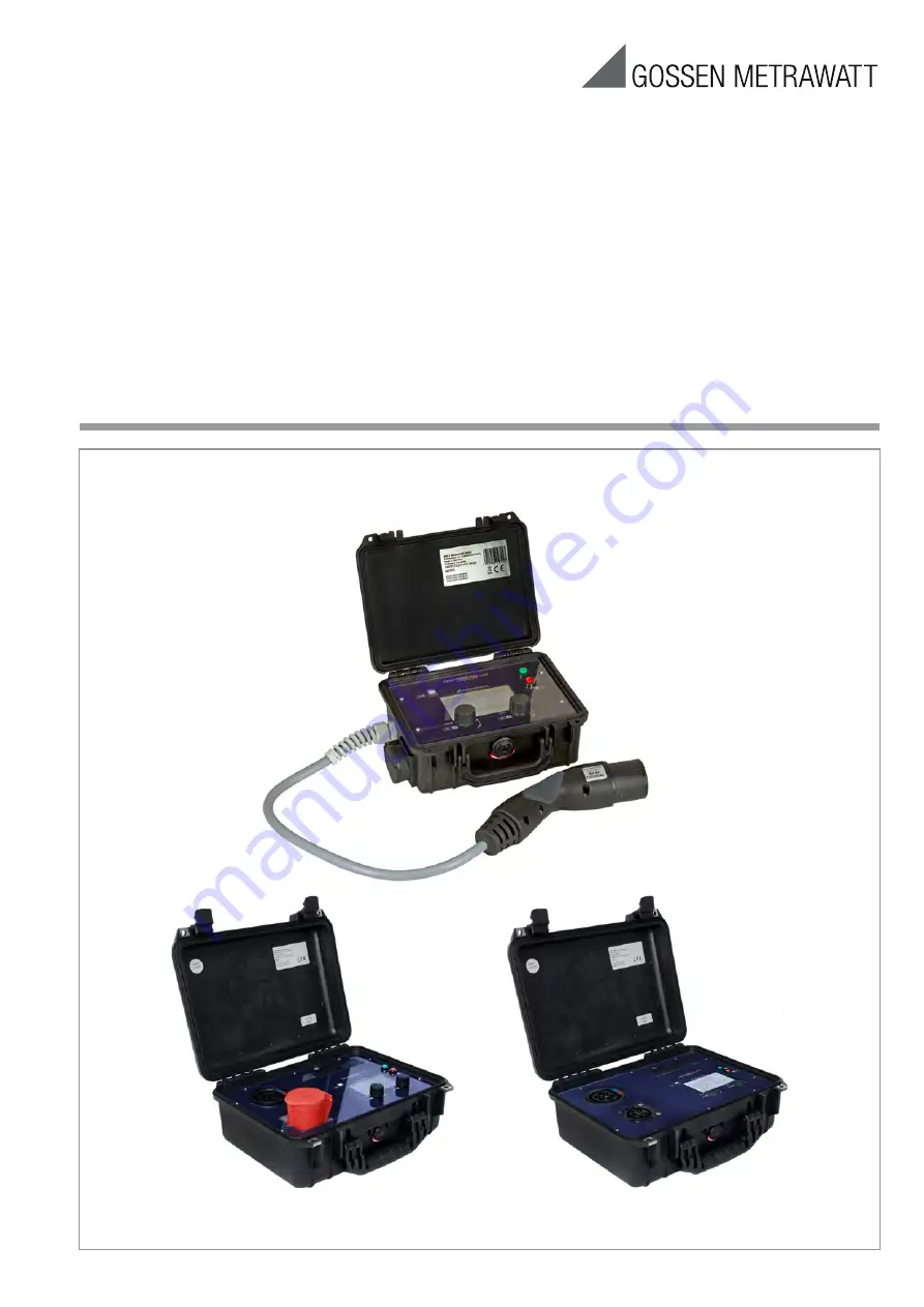
PROFITEST H+E BASE, H+E BASE 32, H+E BASE C
Diagnostics Unit for Electric Charging Stations
3-349-876-03
2/8.20
Страница 1: ...Operating Instructions PROFITEST H E BASE H E BASE 32 H E BASE C Diagnostics Unit for Electric Charging Stations 3 349 876 03 2 8 20 ...
Страница 2: ...device law This device is subject to the WEEE direc tive Furthermore we make reference to the fact that the current status in this regard can be accessed on the Internet at www gossenmetrawatt com by entering the search term WEEE We identify our electrical and electronic devices in accordance with WEEE 2012 19 EU and ElektroG using the symbol shown at the right per DIN EN 50419 These devices may n...
Страница 3: ...al Information on Testing Charging Points 18 General Notes These operating instructions include important information about your device s features and its use Before using the device read the instructions carefully and familiarize yourself with its operation Keep these operating instruction in a safe place Explanation of Symbols This product fulfills guidelines in accordance with 89 336 EEC Warnin...
Страница 4: ...or socket for PROFITEST H E BASE H E BASE 32 or H E BASE C type 1 connector socket for H E BASE C Use for other purposes is prohibited Target Group Only trained qualified electricians may use the PROFITEST H E BASE H E BASE 32 and or H E BASE C diagnostics unit Trained qualified electricians fulfill the following requirements Knowledge of general and specific accident prevention regulations Knowle...
Страница 5: ... block batteries 12 V power pack Operating instructions PROFITEST H E BASE Device Layout Key 1 Protective cover 2 Power pack connector socket 12 V 1 A 3 Battery compartment for two 9 V block batteries 4 Control panel 5 Carrying handle 6 Earthing contact socket 230 V max 13 A for connecting a test consumer 7 Type 2 charging plug for connection to the charging point 1 2 3 4 7 5 6 ...
Страница 6: ... pack connector socket 12 V 1 A 3 Battery compartment for two 9 V block batteries 4 Control panel 5 Carrying handle 6 CEE socket 400 V max 32 A for connecting a test consumer1 7 Type 2 charging plug for connection to the charging point 2 1 Cable not included in the scope of supply 2 Cable not included in the scope of supply 1 2 3 4 5 6 7 ...
Страница 7: ...pack connector socket 12 V 1 A 3 Battery compartment for two 9 V block batteries 4 Control panel 5 Carrying handle 6 Type 1 charging plug for connection to the charging point 3 7 Type 2 charging plug for connection to the charging point 4 3 Cable not included in the scope of supply 4 Cable not included in the scope of supply 1 2 3 4 5 6 7 ...
Страница 8: ...el Layout PROFITEST H E BASE H E BASE 32 H E BASE C Key 1 Rotary mode selector switch and OK button 2 Rotary status selector switch and escape button 3 Off button 4 On button the button has to be pressed and held for several seconds in order to switch the unit on 5 Display 6 USB port ...
Страница 9: ...Operating Instructions PROFITEST H E BASE H E BASE 32 H E BASE C Page 7 Display Layout The display is subdivided into various blocks 1 Vehicle States 2 Cable Condition 3 Error States ...
Страница 10: ...Operating Instructions PROFITEST H E BASE H E BASE 32 H E BASE C Page 8 4 PWM Signal Evaluation 5 Phases and Phase Sequence 6 Battery Level ...
Страница 11: ...e following symbols with the meanings shown below can appear at the display Vehicle States No vehicle connected Vehicle connected Vehicle not ready Vehicle ready to charge No ventilation required Ventilation required Cable Condition No cable 13 A cable 20 A cable 32 A cable 63 A cable ...
Страница 12: ...tes Diode OK Diode short circuited CP OK CP short circuited to PE No RCD tripping RCD tripping Phases and Phase Sequence Phase L1 switched on Phase L2 switched on Phase L3 switched on Clockwise phase sequence Counterclockwise phase sequence Battery Level Battery full Battery depleted ...
Страница 13: ...A 12 V power pack is included in scope of delivery of the diagnostics unit The device can be operated with either batteries or the power pack The power pack is connected by inserting its plug into the socket 2 The batteries are disconnected from supply power when the power pack is connected Warning Use only the included power pack in order to avoid damage to the diagnostics unit Switching the Diag...
Страница 14: ...nit Charging points can be tested in accordance with IEC 61851 with the help of the PROFITEST H E BASE H E BASE 32 and or H E BASE C diagnostics unit The diagnostics unit makes the following functions available Vehicle Simulation CP States A B C and D can be simulated in accordance with IEC 61851 Symbols corresponding to the various vehicle states appear at the display see pages 7 and 9 Display St...
Страница 15: ...quipped with an option for simulating common errors see pages 7 and 10 These include Short circuiting of the diode in the vehicle s circuit Short circuit between CP and PE Residual current between L1 and PE via a 6 8 K resistor The charging point s reaction can be observed after triggering the various errors Display Simulated Error No error Short circuited diode CP PE short circuit Residual curren...
Страница 16: ...th the opposite preceding sign PWM frequency The valid PWM frequency should be 1000 Hz Charging current Displayed charging current is calculated from the duty cycle See explanation under duty cycle Duty cycle In accordance with IEC 61851 the charging point communicates the maximum permissible charging current to the vehicle via the duty cycle Charging current is calculated automatically by the dia...
Страница 17: ... selector switch 1 The respectively active more is indicated by means of a blinking display As shown on pages 7 and 9 there are 3 operating modes Vehicle states Cable condition Error states Within each operating mode the respective state is selected by turning the rotary status selector switch 2 The selection of error states with the rotary switch must also be subsequently acknowledged by pressing...
Страница 18: ...ing the OK button 1 The diagnostics unit is then restarted automatically with the selected language The selected language is retained until a different language is once again selected Errors Error Cause Required Action After being switched on the device switches itself back off again On button not pressed long enough Press and hold the on button until the device remains on The device does not resp...
Страница 19: ...voltage 400 V DC Test voltage 500 V DC Measuring category CAT III 300 V Pollution degree 2 Ambient Conditions Operating temperature 10 to 45 C Storage temperature 25 to 60 C Relative humidity Up to 80 no condensation Mechanical Design Dimensions W x L x H H E BASE 200 mm x 240 mm x 115 mm H E BASE 32 H E BASE C 340 x 410 x 170 mm Weight H E BASE 2 35 kg H E BASE 32 5 35 kg H E BASE C 5 20 kg Prote...
Страница 20: ... 5 W 1 2 330 Ω 1 kΩ 32 A 220 Ω 0 5 W 1 2 150 Ω 330 Ω 63 A 3 phase 70 A 1 phase 100 Ω 0 5 W 1 2 75 Ω 150 Ω Interrupt power supply 75 Ω 1 The power dissipation of the resistor caused by the detection circuit shall not exceed the value given above The value of the pull up resistor shall be chosen accordingly 2 Upon circuit failure mode resistors used should preferably fail such that the resistance va...
Страница 21: ...Operating Instructions PROFITEST H E BASE H E BASE 32 H E BASE C Page 19 Typical Pilot Electric Equivalent Circuit for Mode 3 Charging Typical pilot electric equivalent circuit Source IEC 61851 ...
Страница 22: ...ing ventilation R3 1 300 1261 1339 Ω Switched resistor value for vehicles requiring ventilation R3 270 261 9 278 1 Ω Equivalent total resistor value no ventilation Figure A 2 Re 882 856 908 Ω Equivalent total resistor ventilation required Figure A 2 Re 246 239 253 Ω Diode voltage drop 2 75 10 mA 40 C to 85 C Vd 0 7 0 55 0 85 V Maximum total equivalent input capacity Cv 2 400 N A pF Value ranges ar...
Страница 23: ...d D2 yes ready off 3 Vc 12 Ve PMW E yes N A no not ready off 0 V Steady voltage Vb 0 EVSE or utility problem or utility power not available or pilot short to earth F yes N A no not ready off N A 12 V Steady voltage EVSE not available a All voltages are measured after stabilization period b The EVSE generator may apply a steady state DC voltage or a 12 V square wave during this period The duty cycl...
Страница 24: ...9 8 9 10 States C1 C2 positive 5 47 6 6 53 5 6 7 States D1 D2 positive 2 59 3 3 28 2 3 4 State E 0 0 1 1 0 1 States A2 B2 C2 D2 negative State F a 12 6 12 11 4 13 12 11 a applicable to Va only Note the EVSE may also be designed to use the voltage of the internal generator Vg as a reference The valid voltage ranges are then to be calculated as given in the following table These ranges are identical...
Страница 25: ... duty cycle 85 available current duty cycle x 0 6 A 85 duty cycle 96 available current duty cycle 64 x 2 5 A 96 duty cycle 97 80 A duty cycle 97 Charging not allowed If the PWM signal is between 8 and 97 the maximum current may not exceed the values indicated by the PVM even if the digital signal indicates a higher current In 3 phase systems the duty cycle value indicates the current limit per eac...
Страница 26: ...Operating Instructions PROFITEST H E BASE H E BASE 32 H E BASE C Page 24 System States Duty Cycle ...
Страница 27: ...ore than just a simple electrical outlet and it only functions when a vehicle is detected The diagnostics unit is capable of simulating a vehicle Diagnosis The evaluation of the PWM signal the cable coding for the phases turn off times and the direction of phase rotation are significant with regard to diagnosis The diagnostics unit displays this information ...
Страница 28: ...SE H E BASE 32 H E BASE C Page 26 Diagnosis Procedure for a Charging Point Switch back and forth between states Check parameters and turn off times Switch back and forth between cables Check parameters Trigger errors Check system performance ...
Страница 29: ...ting Instructions PROFITEST H E BASE H E BASE 32 H E BASE C Page 27 Error diagnosis Error L2 not connected or fuse L2 blown Error diagnosis Error No PWM signal Signal generation or cable connection defective ...
Страница 30: ...32 H E BASE C Page 28 Error diagnosis Error Incorrect values for duty cycle and charging current Cable detection defective Error diagnosis Error Erroneous values for PWM voltage and frequency Signal generation defective or CP and PP connections reversed ...
Страница 31: ...atives or subsidiaries for service in other countries DAkkS calibration laboratory for electrical quantities registration no D K 15080 01 01 accredited per DIN EN ISO IEC 17025 2005 Accredited quantities direct voltage direct current value direct current resistance alternating voltage alternating current value AC active power AC apparent power DC power capacitance frequency and temperature Product...
Страница 32: ...is available on the Internet All trademarks registered trademarks logos product names and company names are the property of their respective owners GMC I Messtechnik GmbH Südwestpark 15 90449 Nürnberg Germany Phone 49 911 8602 111 Fax 49 911 8602 777 E Mail info gossenmetrawatt com www gossenmetrawatt com ...