64
GMC-I Gossen-Metrawatt GmbH
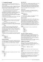
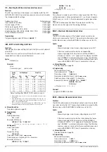
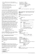
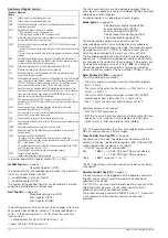
b) Via the IEC bus interface as addressed interface command
GET (GROUP EXECUTE TRIGGER)
Programming examples (HP Basic):
TRIGGER 712
!triggers the device
!with address 12
TRIGGER 7
!all listener addressed
!devices will be triggered
Comment
If trigger action has not been defined (empty DDT memory), bit 4
(EXE, execution error) is set in the standard event register upon
receipt of the device trigger command.
The *TRG command may not be used as part of the DDT
command.
The DDT register is not changed or cleared when the trigger
command is executed.
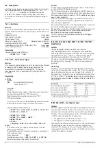
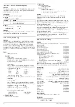
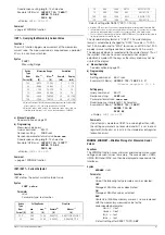
*TST?, HID_TST? – Starting the Self-Test
Functions
Upon receipt of the *TST? or HID_TST? query command, the
device starts a self-test and reads out test results to the output
buffer as a response string.
The *TST? query generates a response of either “0” (= test
passed) or “1” (= test failed).
The response string for the HID_TST? query consists of a
comprehensive list of test results for the individual test steps.
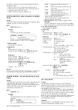
a) ROM Test
The processor acquires the checksum for the ROM module
(program memory), and compares it with the specified value. If
these two values are not identical, correct functioning of the
device cannot be assured and the test failed message appears
(FAILED). If this is the case, the device must be tested at a
service center and repaired if necessary.
b) RAM Test
RAM modules are tested for defective memory locations. If
defective memory locations are detected, correct functioning
of the device cannot be assured and the test failed message
appears (FAILED). If this is the case, the device must be tested
at a service center and repaired if necessary.
c) ADC Timer Test
Analog-digital conversion (ADC) for acquiring measured values
is based upon the voltage-frequency conversion principle
(VFC). The frequency signal is fed to a counter in the CPU.
Gating time is checked at this counter during the ADC timer
test. If gating time is not within the prescribed tolerance,
measuring function accuracy cannot be assured and the test
failed message appears. If this is the case, the device must be
tested at a service center and repaired if necessary.
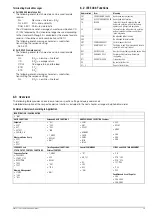
d) DAC/ADC Test
no longer available for firmware version 03.002 and as from
March 2004.
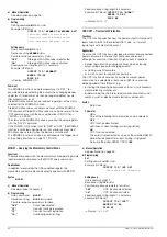
Triggering and Query via the Interfaces
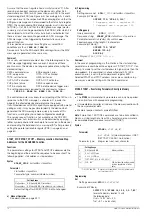
a) Query command:
*TST?
Response string:
0 = test passed
1 = test failed
Fixed response string length: 1 character
b) Query command:
HID_TST?
Sample response string:
"X-ROM-TEST PASSED (0B800H); X-RAM-TEST
PASSED; ADC-TIMER-TEST PASSED; DAC-ADC-
TEST PASSED (000000000); END TEST"
Fixed response string length: 111 characters
Comment
Starting the self-test does not cause any changes to current
device settings or stored parameters.
The self-test sequence is started immediately after receipt of the
corresponding query command and has a duration of
approximately 6 seconds. The “READY” LED blinks during the
self-test triggered with the HID_TST? command.
As long as the test is running, no data can be transmitted to the
device and manual operation is disabled.
Programming Notes
Do not transmit the *TST? or HID_TST? command together with
other settings and/or query commands in a single string.
Enter a waiting period of approximately 6 seconds between
transmission of the query commands and read-out of the
response string, or in the event of IEC bus operation:
Completion of the self-test can be recognize by means of cyclical
querying and evaluation of the status byte (serial polling) (test
completed
→
MAV-Bit = 1). The self-test is not influenced by
serial polling.
If the self-test is failed, the “TSTE” bit is set in event register B. An
SRQ is generated in the event of appropriate masking by means
of enable registers ERDE and SRE.
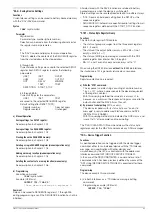
*WAI – Wait to Continue
Functions
The
*WAI
command is of no significance for programming the
KONSTANTER.
It serves to synchronize the interface protocol in accordance with
the IEC 488.2 standard.
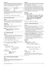
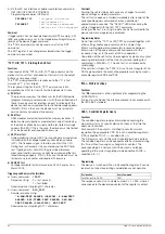
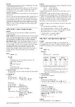
CRA? – Condition Register Query
Functions
The condition register provides information concerning the
momentary status of specific device functions at the time the
query was executed.
For example, if the output is switched to constant current
regulation, the appropriate CCR bit is set in condition register A
(CRA) (condition TRUE —> condition bit = 1).
This bit remains set until the current regulating mode is exited.
The condition register can be queried as often as desired during
this time, without causing any change to its content. The
corresponding bit is not reset until the output is no longer
operating in the current regulating mode (condition FALSE
→
condition bit = 0).
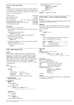
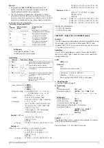
Programming
The device is furnished with an 8-bit condition register. It can be
read out, but direct overwriting and deletion are not possible.
The response consists of a whole number 0
≤
n
≤
255, where
n
corresponds to the decimal equivalent of the register’s content.
Designation
Query Command
Condition register A (CRA)
CRA?
Содержание 62 N Series
Страница 2: ...2 GMC IGossen MetrawattGmbH ...
Страница 81: ...GMC I Gossen Metrawatt GmbH 81 PCB G ...
Страница 82: ...82 GMC I Gossen Metrawatt GmbH PCB A Uout max Uout 0 Iout max Iout 0 ...

