GMC-I Gossen-Metrawatt GmbH
53
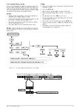
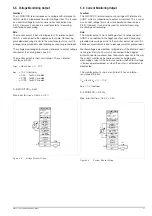
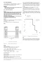
5.8 Parallel Connection
If output current from a single KONSTANTER is insufficient for the
respective application, the outputs of any number of
KONSTANTERs can be parallel connected.
Caution!
If outputs with different nominal voltages are parallel connected, all
outputs must be limited to the lowest utilized nominal voltage value.
The ULIM parameter is used to select this setting.
5.8.1
Direct Parallel Connection
Functions
Easiest way to provide the power consumer with more current
than is available from a single KONSTANTER.
KONSTANTERs with differing nominal output voltages can be
used. However, all voltage setpoints must be set or limited to the
same value.
This setup is less suitable for the constant voltage regulating
mode.
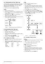
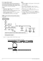
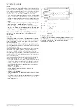
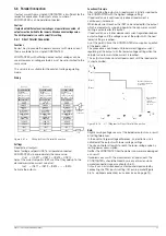
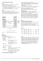
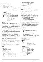
Wiring
Figure 5.8.1a
Wiring for Direct Parallel Connection
Settings
Deactivate all outputs.
Adjust voltage setpoint USET of all parallel connected
KONSTANTERs to approximately the same value:
Uset = USET1 = USET2 = USET3 = USETn
Adjust the current setpoints ISET such that they add up to the
desired cumulative current value Iset:
Iset
= ISET1 + ISET2 + ISET3 + ... + ISETn
Activate the outputs.
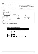
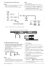
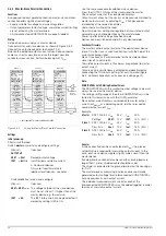
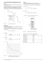
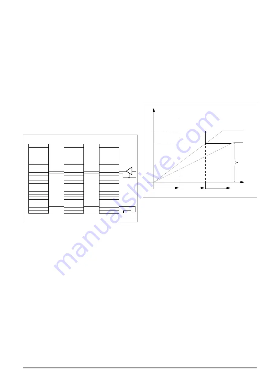
Functional Principle
After switching the outputs on, load current is initially supplied by
the KONSTANTER with the highest voltage setting.
If load resistance is continuously reduced, load current is
continuously increased.
When load current reaches the ISET value selected for the output
which is momentarily supplying power to the consumer, current
limiting is activated for this output.
If load resistance is further decreased, current regulation reduces
output voltage until the voltage value of the output with the next
lowest setting is reached.
As of this point in time, this KONSTANTER also supplies a portion
of the load current.
This procedure is continued until load current triggers current
regulating at the output with the lowest voltage setting when the
setpoint value for cumulative current is reached.
This output maintains constant load current until the load resistor
is short-circuited.
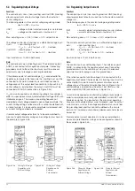
Figure 5.8.1b
U / I Diagram for Direct Parallel Connection
Note:
Slightly varying voltages occur at the individual outputs as a result
of setting tolerances.
In the event of larger voltage differences, an electronic sink is
activated at the outputs with lower voltage settings.
The sink controller attempts to reach the lower voltage value by
limiting power consumption.
Neither the KONSTANTER nor the power consumer are damaged
as a result.
If problems occur with the measurement of load current, the
KONSTANTERs should be linked by means of master-slave
parallel connection (see also chapter 5.8.2).
Outputs can be simultaneously activated and deactivated by
connecting the TRG inputs (setting: trG out) in parallel (Figure
5.8.1a, optional connection) or in series (see also page 74).
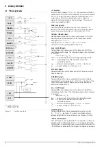
Analog Interface
+15 V
AGND
T
TRIGGER
−
Uset +
Uset GND
M/S Uset +
Settings:
USET = Uset
ISET1+2+3=Iset
OUTPUT on/off
SSP KONSTANTER
−
SENSE
+SENSE
U-MONITOR
Iset +
Iset GND
+OUT
I-MONITOR
–OUT
Device 3
Analog Interface
+15 V
AGND
T
TRIGGER
−
Uset +
Uset GND
M/S Uset +
Settings:
USET = Uset
ISET1+2+3=Iset
OUTPUT on/off
SSP KONSTANTER
−
SENSE
+SENSE
U-MONITOR
Iset +
Iset GND
+OUT
I-MONITOR
–OUT
Device 2
Analog Interface
+15 V
AGND
T
TRIGGER
−
Uset +
Uset GND
M/S Uset +
Settings:
USET = Uset
ISET1+2+3=Iset
OUTPUT on/off
Load
SSP KONSTANTER
−
SENSE
+SENSE
U-MONITOR
Iset +
Iset GND
+OUT
I-MONITOR
–OUT
Device 1
Optional
Connection
Ideal working
current
regulation at
Ideal working range
for voltage regulation
at the load
U
out1
U
out2
U
out3
I
out1
I
out2
I
out3
R
L
R
L
U
A
/ V
I
A
/ A
range for
the load
Содержание 62 N Series
Страница 2: ...2 GMC IGossen MetrawattGmbH ...
Страница 81: ...GMC I Gossen Metrawatt GmbH 81 PCB G ...
Страница 82: ...82 GMC I Gossen Metrawatt GmbH PCB A Uout max Uout 0 Iout max Iout 0 ...