52
GMC-I Gossen-Metrawatt GmbH
5.7 Trigger Input
Functions
The floating T
input with optocoupler allows for remote
control of a device function by means of a binary signal.
The function to be controlled is selected with the T_MODE setting
(in the trG display).
A detailed description is included on page 74.
Connection
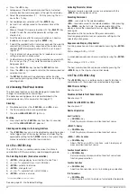
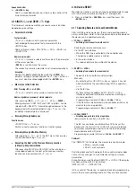
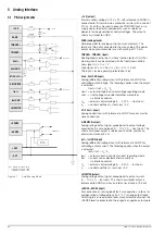
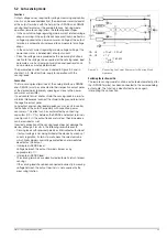
Connect the control signal to T and TRIGGER –.
Refer to the table below for the respective signal level.
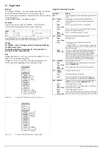
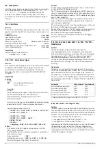
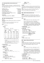
The TRIGGER input can be driven with the + 15 V output at the
analog interface via any desired switch (Figure 5.7a).
Warning!
The T input is a floating input and is functionally isolated from
the output current circuit.
This functional isolation is not equivalent to “safety separation” as
specified in electrical safety regulations.
Note
Trigger signal pulses must have a minimum duration of 14 ms in
order to assure reliable recognition.
A delay of 1 to 15 ms may occur between application of the
control signal and triggering of the controlled function.
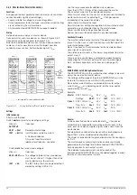
Figure 5.7a
Driving the TRIGGER Input with a Switch Contact
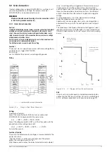
Figure 5.7b
Driving the TRIGGER Input with an External Signal
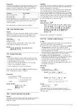
Trigger Function setting Parameters
Signal
U
S
I
S
High
4 ... 26 V DC
(U
S
– 2 V) / 1.5 k
Ω
Low
0 ... 1 V DC
0 mA
Analog Interface
+15 V
AGND
T
TRIGGER
−
Uset +
Uset GND
M/S Uset +
Settings:
USET = Uset
ISET = Iset
T_MODE
≠
OFF
I
S
= 10 mA
Load
SSP KONSTANTER
−
SENSE
+SENSE
U-MONITOR
Iset +
Iset GND
+OUT
I-MONITOR
–OUT
Iout
Analog Interface
+15 V
AGND
T
TRIGGER
−
Uset +
Uset GND
M/S Uset +
Settings:
USET = Uset
ISET = Iset
T_MODE
≠
OFF
I
S
Load
SSP KONSTANTER
−
SENSE
+SENSE
U-MONITOR
Iset +
Iset GND
+OUT
I-MONITOR
–OUT
Iout
U
S
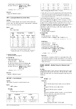
Parameter
Meaning
OFF
Trigger input function is deactivated, trigger signals have no
effect.
OUT
OUTPUT
Trigger signal acts upon the OUTPUT: output On/Off
Low
OUTPUT depends upon manual setting or programming
command
Edge
Low
→
High
OUTPUT remains OFF or OUTPUT is switched OFF
High
OUTPUT is OFF and cannot be activated (neither manually nor
by means of a program command).
Edge
High
→
Low
OUTPUT is activated, exception: OTP or OVP
RCL
RECALL
Memory recall (step-by-step sequence control)
Edge
Low
→
High
Start trigger signal
High
– The trigger signal is a high pulse with a duration
of 11 to 800 ms.
– A pulse with t
high
> 1.0 s resets the address counter to the
start address at any point in time, and execution begins with
the next trigger signal.
Edge
High
→
Low
The high
→
low edge of the (short) trigger signal results in
step-by-step control of the currently selected sequence,
regardless of the specified time and number of repetitions.
Recall of the memory’s contents begins with the START
address. Each trigger signal increasers the address by 1, until
the STOP address is reached. The next pulse once again
causes execution of the contents of the START address.
SEQ
SEQUENCE
Sequence execution control
Edge
Low
→
High
The SEQUENCE function is started beginning with the start
address (
SEQUENCE GO
).
Edge
High
→
Low
Ends sequence execution by jumping to the stop address
LLO
LOCAL
LOCKED
Front panel control disabling
Low
All front panel controls are functional.
High
All front panel controls are disabled except for the mains
switch, and activation is not possible with the
LOCAL
key.
MIN
MINMAX
Storage of Min-Max values for U and I is controlled when the
MINMAX function is activated (
MINMAX ON
)(
UI_
ON).
Low
The Min-Max function is active.
Edge
Low
→
High
The Min-Max function is deactivated. Values in the Min-Max
memories remain unchanged.
High
The Min-Max function is inactive.
Edge
High
→
Low
Values in the Min-Max memories are reset and replaced with
momentary output values. The Min-Max function is activated.
Содержание 62 N Series
Страница 2: ...2 GMC IGossen MetrawattGmbH ...
Страница 81: ...GMC I Gossen Metrawatt GmbH 81 PCB G ...
Страница 82: ...82 GMC I Gossen Metrawatt GmbH PCB A Uout max Uout 0 Iout max Iout 0 ...

