Gomax EX-57V2K-U Скачать руководство пользователя страница 7

5


Receiving unit ► EX-57V2K-U-RX 
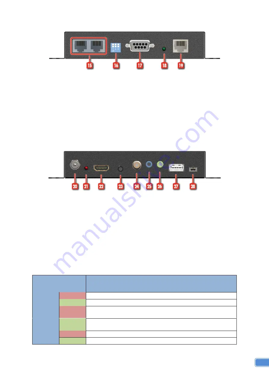
 

Front Panel 


15. Ethernet port for LAN: 

Connect to network device


16. DIP Switch:

 PIN#1: Setup the USB communication 

PIN#2: Setup the RS-232 mode for serial communication channel 
PIN#3: For Firmware Update 


17. RS-232:

 Connect to serial port device with a DSUB-9 male-male or male-female cable here


        F/W update for Valens chipset


18. LED: 

TX/RX link indicator


19. RJ45: 

Plug in a Cat-5/5e/6 cable that needs to be linked to the transmitting unit TX.


Rear Panel 


20. +24V DC: 

Connect to a 24V DC power supply.


21. LED: 

Power indicator


22. HDMI OUT:

 Connect to a HDMI display with a HDMI male-male cable


23. Stereo: 

Analog audio output


24. RCA connector: 

local ARC output


25. IR Blaster:

 Infrared 3.5mm socket for plugging in the extension cable of IR blaster


26. IR Receiver:

 Infrared 3.5mm socket for plugging in the extension cable of IR receiver


27. USB: 

Connect to USB Device


28. Mini-USB: 

Connect to USB Host 

*

 DIP Switch Position (TX/RX)


DIP Switch Position 

Description 

TX & RX 

PIN#1


ON [

As an USB Host (USB Type-mini-B port) 

OFF [

As an USB Device (USB Type A port) 

PIN#2 

ON [

]


TxD: The 2

nd

 pin of RS-232, which is in charge of sending data 

RxD: The 3

rd

 pin of RS-232, which is in charge of receiving data 

OFF [

]


TxD: The 3

rd

 pin of RS-232, which is in charge of sending data 

RxD: The 2

nd

 pin of RS-232, which is in charge of receiving data 

PIN#3 


ON [

Firmware Update mode 

OFF [

Working mode 


Содержание EX-57V2K-U

Страница 1: ...HDBaseT 2 0 Extender with RS232 Bi directional IR Ethernet PoC USB User Manual rev 150805 Made in Taiwan EX 57V2K U...

Страница 2: ...vice this unit yourself except where explained in this manual Provide proper ventilation and air circulation and do not use near water Keep objects that might damage the device and assure that the pla...

Страница 3: ...ch panels In addition EX 57V2K U also supports PoC Power over Cable which can power both units from TX or RX with power supply The EX 57V2K U includes two units transmitting unit EX 57V2K U TX and rec...

Страница 4: ...Either on TX or RX Input 1x HDMI 2x 3 5mm 1x RJ 45 Video 1x 3 5mm Output 1x RJ 45 Video 1x 3 5mm 1x SPDIF 1x HDMI 2x 3 5mm 1x SPDIF In Out 1x RS 232 2x USB 2x RJ 45 Ethernet 1x RS 232 2x USB 2x RJ 45...

Страница 5: ...3 PACKAGE CONTENTS 1x EX 57V2K U TX RX 1x IR blaster 1x IR receiver 1x DC 24V1A 1x User Manual CONNECTION DIAGRAM...

Страница 6: ...s chipset 4 LED TX RX link indicator 5 RJ45 Plug in a Cat 5 5e 6 cable that needs to be linked to the transmitting unit RX Rear Panel 6 24V DC Connect to a 24V DC power supply 7 LED Power indicator 8...

Страница 7: ...ith a HDMI male male cable 23 Stereo Analog audio output 24 RCA connector local ARC output 25 IR Blaster Infrared 3 5mm socket for plugging in the extension cable of IR blaster 26 IR Receiver Infrared...

Страница 8: ...e controls of the corresponding devices Definition of IR Earphone Jack IR Blaster IR Receiver You can buy any IR extension cables in the market that are compatible to the definition of the IR sockets...

Страница 9: ...ARE INSTALLATION 1 Connect a HDMI or DVI source such as a Blu ray Disc player to the transmitting unit EX 57V2K U TX 2 Connect a HDMI or DVI display such as a LCD TV to the receiving unit EX 57V2K U R...

Страница 10: ...TP Cat 5e cable shows longer transmission range than stranded STP Cat 6 cable For long extension applications solid UTP STP cables are the only viable choice 4 EIA TIA 568 B termination T568B for Cat...

Страница 11: ...nsure the unit or assume the risk of loss or damage in transit Under no circumstances will a unit be accepted without a return authorization number The warranty is in lieu of all other warranties expr...

Отзывы: