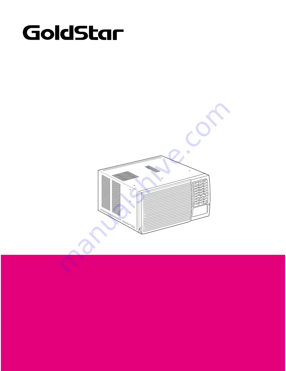
ROOM AIR CONDITIONER
SERVICE MANUAL
CAUTION
• BEFORE SERVICING THE UNIT, READ THE SAFETY PRECAUTIONS
IN THIS MANUAL.
• ONLY FOR AUTHORIZED SERVICE PERSONNEL.
MODEL: BG8000ER, WG8005R,
WG1005R, WG1205R
website http://www.lgservice.com
Страница 1: ...CONDITIONER SERVICE MANUAL CAUTION BEFORE SERVICING THE UNIT READ THE SAFETY PRECAUTIONS IN THIS MANUAL ONLY FOR AUTHORIZED SERVICE PERSONNEL MODEL BG8000ER WG8005R WG1005R WG1205R website http www lgservice com ...
Страница 2: ...he Drain Pipe 8 How to Install 9 Operation 13 Location and Function of Controls 13 Remote Control Operations 14 Disassembly 15 Mechanical Parts 15 Air Handling Parts 16 Electrical Parts 17 Refrigerating Cycle 19 Schematic Diagram 22 Wiring Diagram 22 Electronic Control Device 24 Components Location For Main P W B ASM 25 Troubleshooting Guide 26 Piping System 26 Troubleshooting Guide 27 Exploded Vi...
Страница 3: ...ibility of death or serious injury This symbol indicates the possibility of injury or damage to property only WARNING Always install the expansion panel s Improper assembly or installation may cause incorrect operation including injury fire and Do not place the power cord near a heater It may cause fire and electric shock Do not use the power cord near flammable gas or combustibles such as gasolin...
Страница 4: ...d It may cause fire and electric shock Do not operate with wet hands or in damp environment It will cause electric shock Use the air conditioner on a single outlet circuit see page 7 Do not share the outlet with other appliances It will cause electric shock or fire Do not modify power cor Do not modify po Do not modify po d wer cor length Do not modify po It will cause electric shoc k or fire Alwa...
Страница 5: ...er the unit and degrade the insulation It may cause an electric shock Never touch the metal parts of the unit when removing the filter Do not block the inlet or outlet They are sharp and may cause injury It may cause failure of appliance or performance deteriorate Ensure that the outer caseis not damaged by age orwear Leaving it damaged couldresult in the air conditioner falling out of the window ...
Страница 6: ...de Dimensions This symbol alerts you to the risk of electric shock This symbol alerts you to hazards that could cause harm to the air conditioner This symbol indicates special notes NOTICE Symbols Used in this Manual 353 13 7 8 470 18 1 2 525 20 11 16 ...
Страница 7: ...10 8 9 8 26 7 DB 19 4 WB 35 DB 23 9 WB 385g 13 6oz 260g 9 2oz 440g 15 5oz 380g 13 4oz Ø9 52 2ROW 12STACKS Ø7 0 2ROW 14STACKS Ø7 0 2ROW 16STACKS Ø5 0 2ROW 16STACKS Ø7 2R 16STACKS 5 2R 18STACKS Ø7 3R 14STACKS 7 2R 14STACKS TURBO FAN PROPELLER TYPE FAN WITH SLINGER RING 3 3 6 POLES REMOTE CONTROLLER THERMISTOR HORIZONTAL LOUVER UP DOWN VERTICAL LOUVER RIGHT LEFT SLIDE IN OUT CHASSIS OVERLOAD PROTECTO...
Страница 8: ...lower than the front about 1 4 This will force condensed water to the outside 5 Install the unit with the bottom about 30 60 above the floor level The setting conditions must be checked prior to initial starting The following items are especially important checking points when the installation is finished 1 Grounding wire Green or Green and Yellow is provided in the power cord The green wire must ...
Страница 9: ... OUT DOORS to help condensation to drain properly to the outside 3 Install a second wood strip approximately 6 long by 11 2 wide and same thickness as first strip in the center of the outer sill flush against the back off the inner sill This will raise the L bracket as shown Figure 4 4 If the distance between STORM WINDOW FRAME and WOOD STRIP MOUNTED ON TOP OF INNER SILL is more than 1 two of wood...
Страница 10: ...he cabinet 7 Insert the Frame Curtain into the Upper Guide and Frame Guides 8 Fasten the curtains to the unit with 4 Type A screws CABINET INSTALLATION 1 Open the window Mark a line on center of the window stool or desired air conditioner location Carefully place the cabinet on the window stool and align the center mark on the bottom front with the center line marked in the window stool 2 Pull the...
Страница 11: ...igure 8 6 The cabinet should be installed with a very slight tilt about 1 2 downward toward the outside See Figure 9 Adjust the bolt and the nut of Sill Support for balancing the cabinet 7 Attach the cabinet to the window stool by driving the screws Type B Length sixteen millimeters and below through the front angle into window stool 8 Pull each Frame Curtain fully to each window sash track and re...
Страница 12: ... the cabinet by inserting the tabs on the grille into the tabs on the front of the cabinet Push the grille in until it snaps into place See Figure 14 14 Lift the inlet grille and secure it with a Type A screw through the front grille See Figure 15 15 Window installation of room air conditioner is now completed See ELECTRICAL DATA for attaching power cord to electrical outlet Figure 11 Figure 12 Fi...
Страница 13: ...Turn the operation switch to the Low Cool setting 2 Set the thermostat control as needed DESIGNED FOR COOLING ONLY POWERFUL AND INCREDIBLE COOLING TOP DOWN CHASSIS FOR THE SIMPLE INSTALLATION AND SERVICE BUILT IN ADJUSTABLE THERMOSTAT WASHABLE ONE TOUCH FILTER COMPACT SIZE Service Manual 13 Operation Off Turns air conditioner off Med Fa n Med speed fan operation without cooling Low Fa n Low speed ...
Страница 14: ...gh the options in this order 1 Hour 2 Hours 3 Hours 4 Hours 5 Hours 6 Hours 7 Hours 8 Hours 9 Hours 10 Hours 11 Hours 12 Hours CANCLE 5 Energy Saver The fan stops when the compressor stops cooling Approximately every 3 minutes the fan will turn on and check the room air to determine if cooling is needed 6 Cool Fan Dry Everytime you push this button it will toggle between COOL FAN and DRY How to In...
Страница 15: ...net at back 3 Pull the base pan forward See Figure 18 4 Remove the cabinet 5 Re install the component by referring to the removal procedure above 3 CONTROL BOX 1 Disconnect the unit from the power source 2 Remove the front grille 3 Remove the cabinet 4 Remove the screw which fastens the control box cover 5 Remove the housing which connects motor wire in the control box 6 Remove the 3 leads from th...
Страница 16: ... remove it See Figure 21 10 Remove the clamp with a hand plier which secures the blower 11 Remove the blower 12 Remove the 4 screws which fasten the air guide from the barrier 13 Move the air guide backward pulling out from the base pan 14 Re install the components by referring to the removal procedure above 2 FAN AND SHROUD 1 Remove the cabinet 2 Remove the brace 3 Remove the 3 screws which faste...
Страница 17: ...ove all the leads from the overload protector 5 Remove the overload protector 6 Re install the component by referring to the removal procedure above Figure 24 Disassembly 2 COMPRESSOR 1 Remove the cabinet 2 Discharge the refrigerant system using a FreonTM Recovery System If there is no valve to attach the recovery system install one such as a WATCO A 1 before venting the FreonTM Leave the valve in...
Страница 18: ...l procedure above See Figure 27 Figure 27 Figure 26 1 Remove the control box 2 Remove the knobs and the screw which fasten control panel from control box 3 Remove the screw which is located in the front 4 Open the bottom side of control box 5 Remove the screw and the clamp which fasten the capacitor 6 Disconnect all the leads of capacitor terminals 7 Re install the components by referring to the r...
Страница 19: ...l box 2 Open the control box 3 Disconnect the grounding screw from the control box 4 Disconnect the 2 receptacles 5 Remove a screw which fastens the clip cord See Figure 30 6 Remove the power cord 7 Re install the component by referring to the above removal procedure above Use only one ground marked hole for ground connection 8 If the supply cord of this appliance is damaged it must be replaced by...
Страница 20: ...r final charging 6 Recharge as follows 1 Refrigeration cycle systems are charged from the High side If the total charge cannot be put in the High side the balance will be put in the suction line through the access valve which you installed as the system was opened 2 Connect the charging cylinder as shown in figure 33B With valve C open discharge the hose at the manifold connection 3 Open valve A a...
Страница 21: ...making a vapor proof seal Leak detector Tubing cutter Hand Tools to remove components Service valve A COMPOUND GAUGE EVAPORATOR LOW PRESSURE SIDE COMPRESSOR CAPILLARY TUBE CONDENSER HIGH PRESSURE SIDE SEE INSETS BELOW MANIFOLD GAUGE B Figure 33A Pulling Vacuum Figure 33B Charging A B EXTERNAL VACUUM PUMP A CHARGING CYLINDER LOW HI B C ...
Страница 22: ...S S S LOCATION NO DESCRIPTION REMARKS Q TY PER SET S Service Parts N Non Service Parts MODEL ROTARY SWITCH TYPE MODEL 8 P T C 1 S COMP MOTOR WH BL POWE R INPUT Plain GN GN YL BK BR R ibbed WIR ING DIAGR AM 3854AR 3563A BL R D BK R C S YL YL OR BR R D BK BL B L R D R OTAR Y S WITCH BK BL L 7 1 8 6 4 5 3 2 H M OR BR BL CAPACITOR R D BK F C H BR YL BK OLP THE R MOS TAT 4 5 8 3 2 1 7 P T C GN GN YL R ...
Страница 23: ...ram MODEL TOUCH REMOTE CONTROL TYPE MODEL LOCATION NO 1 2 3 4 5 6 7 8 Q TY PER SET 1 1 1 1 1 1 1 1 DESCRIPTION POWER CORD ASSEMBLY FAN MOTOR COMPRESSOR DISPLAY P W B ASSEMBLY MAIN P W B ASSEMBLY THERMISTOR CAPACITOR OWERLOAD PROTECTOR 1 6 4 5 8 3 7 2 ...
Страница 24: ...24 Room Air Conditioner Electronic Control Device Schematic Diagram ...
Страница 25: ...Service Manual 25 Components Location For Main P W B ASM Schematic Diagram ...
Страница 26: ...e cooling cycle MOTOR COMPRESSOR OIL LIQUID REFRIGERANT CAPILLARY TUBE OUTSIDE COOLING AIR FOR REFRIGERANT PASS THROUGH SUCTION LINE COOL LOW PRESSURE VAPOR COOLED AIR COMPLETE LIQUID BOIL OFF POINT LIQUID PRESSURE DROP ROOM AIR HEAT LOAD VAPOR INLET HOT DISCHARGED AIR LIQUID OUTLET HIGH PRESSURE VAPOR LIQUID REFRIGERANT LOW PRESSURE VAPOR ROOM AIR CONITIONER EVAPORATOR COILS CONDENSER COILS CYCLE...
Страница 27: ...ure difference of inlet outlet air 44 50 F 7 10 C Replacement of unit if the unit is beyond repair Check outdoor coil heat exchanger and fan operation Check heat load increase Check cold air circulation for smooth flow Check gas leakage Clean condenser Not on separate circuit Check inside gas pressure Adjust refrigerant charge Malfunction of compressor Replacement of compressor Check clogging in r...
Страница 28: ...ressor fails only to start Defect of compressor capacitor Replacement of compressor Motor damaged Irregular motor insulation Ω Irregular motor resistance Ω Check of circuit breaker and fuse Check control panel Fan only fails to start Improper wiring Defect of fan motor capacitor Replacement of fan motor Regular but fails to start Replacement of compressor Locking of piston metal Irregular motor re...
Страница 29: ...of IC01D DC 12V Is output Voltage of IC02D DC 5V Is the voltage No 18 of Micom DC 5V Exchange Main P W B Ass y Is the connection between Main and Display all right Is the reset circuit all right The No 14 of Micom is 5V Check the Fuse Check the wiring diagram Check the Main P W B pattern Exchange the Trans Exchange D02D D05D Exchange IC01D Exchange IC02D Exchange IC01A Connect connector exactly Ch...
Страница 30: ...heck the RY COMP Check the wiring Diagram NO NO NO NO YES YES YES YES Possible Trouble 2 The compressor does not operate Is the wire connection of RY COMP all right Check the RY COMP Connect LEAD Wire to RY COMP again NO YES Possible Trouble 3 The compressor always operate Exchange IC01M Exchange IC01M Is the voltage NO 1 or 4 of IC01M DC 5V Is the voltage NO 13 or 16 of IC01M 0V Check the RY Hi o...
Страница 31: ...rn Connect connector to CN DISP1 exactly NO NO NO YES YES YES Possible Trouble 5 Romote controller does not operate NO NO NO NO YES YES YES Is the IC01G all right Is the connection of CN DISP1 all right Exchange the display P W B Ass y Exchange IC01G Exchange Q01G Q02G Q03G Q04G Connect connector to CN DISP1 exactly Does the Q01G Q02G Q03G Q04G operate normally on main P W B Ass y Possible Trouble...
Страница 32: ...oose terminal Capacitor Discharge Test capacitor capacitor before testing Replace if not within 10 of manufacturer s rating Replace if shorted open or damaged Will not rotate Fan blade hitting shroud or blower wheel hitting scroll Re align assembly Units using slinger ring condenser fans must have 0 22 0 25 inch clearance to the base If necessary shim up the bottom of the fan motor with mounting s...
Страница 33: ...ram correct the connections Thermistor Check the TEMP control If not at the lowest number set TEMP control to this setting and restart the unit Check the continuity of the thermistor Replace the thermistor if the circuit is open Rotary Check for continuity refer to the wiring diagram for terminal identification Replace the switch if the circuit is open Thermostat Check the position of knob If not ...
Страница 34: ...r base before re assembling Condenser fins If the condenser fins are closed over a large damaged area on the coil surface head pressures will increase causing the compressor to cycle Straighten the fins or replace the coil Capacitor Test the capacitor Wiring Check the terminals If loose repair or replace Refrigeration system Check the system for a restriction Insufficient cooling Air filter If res...
Страница 35: ...ZZ 135500 249950 149410 359011 552113 552102 35211A 352113 269300 237200 264100 W5210E 2 W5210E 1 731273 267110 749740 135312 147581 147582 135303 152302 349480 130410 550140 554160 567502 349001 354210 W48602 359012 349600 149980 346811 W48602 352380 130910 148000 ...
Страница 36: ...35500 W0CZZ 554030 359011 552113 552102 35211A 352113 567480 264100 W5210E 2 W5210E 1 268711 1 268711 2 731273 267110 749740 147581 147582 135312 135303 152302 349480 130410 550140 554160 567502 349001 354210 W48602 359012 149980 352380 W48602 349600 346811 130910 148000 ...
Страница 37: ...5421AR2910D 5421A20061H 5421A20132B 5421A20061G R 554030 CONDENSER ASSY FIRST 5403A20083D 5403A20092D R 352113 TUBE ASSY DISCHARGE 5211A20644A 5211AR2930Z 5211A21201A 5211A20208D R 35211A TUBE ASSY SUCTION 5211A20643A 5211A20130R 5211A20130S 5211A20130M R 552102 TUBE CAPILLARY BEND 5211A30260W 5211A20598B 5211A30260F 5211A30260B R 552113 TUBE ASSY CONDENSER OUT 5211A10067E 5211AR7059A 5211AR3399A ...
Страница 38: ...P No 3828A26005A December 2004 Printed in China ...