


6A-20 GENERAL ENGINE MECHANICAL
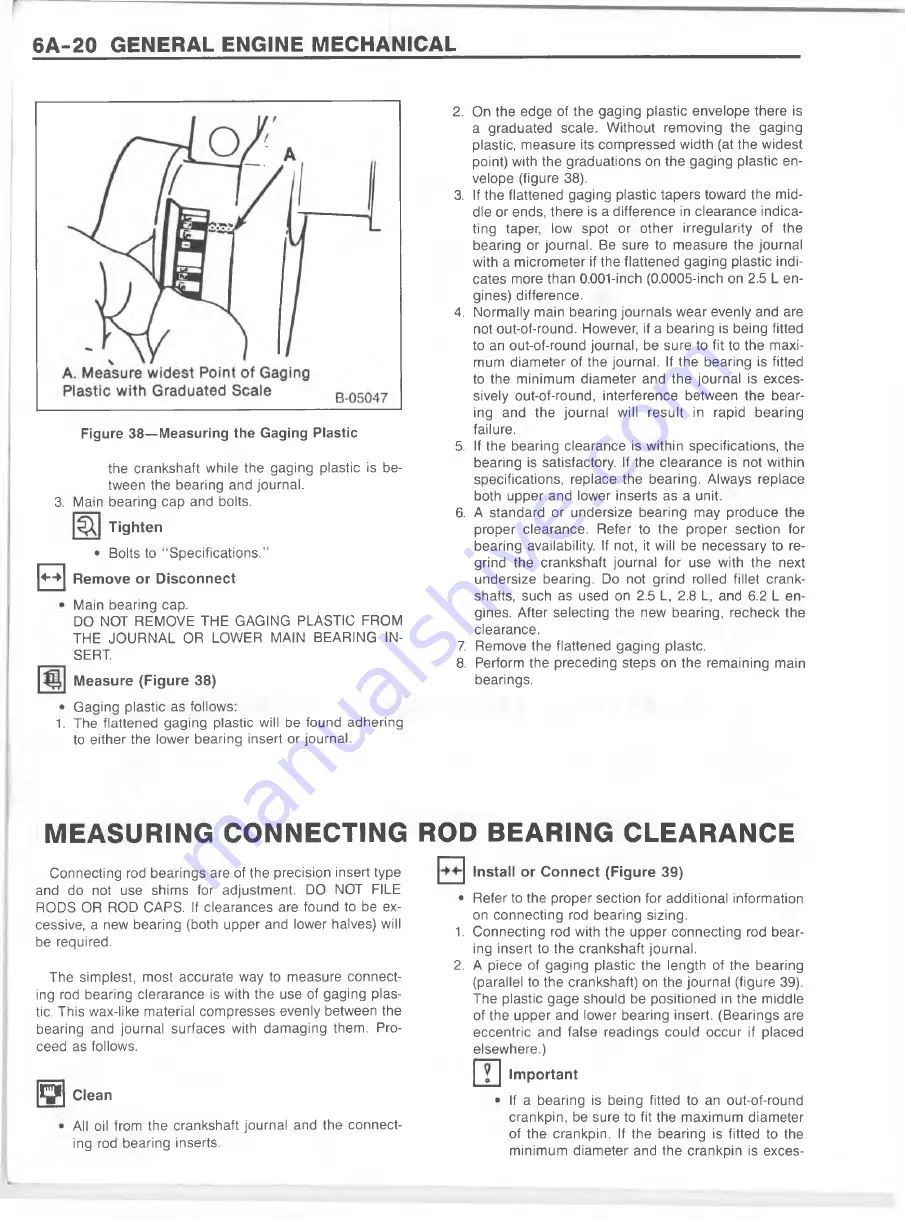
Figure 38— Measuring the Gaging Plastic
the crankshaft while the gaging plastic is be
tween the bearing and journal.
3. Main bearing cap and bolts.
T ig h ten
• Bolts to “ Specifications.”
+-► R em ove or D isconnect
Main bearing cap.
DO NOT REMOVE THE GAGING PLASTIC FROM
THE JOURNAL OR LOWER MAIN BEARING IN
SERT
M easure (Figure 38)
• Gaging plastic as follows:
1. The flattened gaging plastic will be found adhering
to either the lower bearing insert or journal.
2. On the edge of the gaging plastic envelope there is
a graduated scale. W ithout removing the gaging
plastic, measure its compressed width (at the widest
point) with the graduations on the gaging plastic en
velope (figure 38).
3. If the flattened gaging plastic tapers toward the m id
dle or ends, there is a difference in clearance indica
ting taper, low spot or other irregularity of the
bearing or journal. Be sure to measure the journal
with a micrometer if the flattened gaging plastic indi
cates more than 0.001-inch (0.0005-inch on 2.5 L en
gines) difference.
4. Normally main bearing journals wear evenly and are
not out-of-round. However, if a bearing is being fitted
to an out-of-round journal, be sure to fit to the m axi
mum diameter of the journal. If the bearing is fitted
to the minimum diameter and the journal is exces
sively out-of-round, interference between the bear
ing and the journal will result in rapid bearing
failure.
5. If the bearing clearance is within specifications, the
bearing is satisfactory. If the clearance is not within
specifications, replace the bearing. Always replace
both upper and lower inserts as a unit.
6. A standard or undersize bearing may produce the
proper clearance. Refer to the proper section for
bearing availability. If not, it will be necessary to re
grind the crankshaft journal for use with the next
undersize bearing. Do not grind rolled fillet crank
shafts, such as used on 2.5 L, 2.8 L, and 6.2 L en
gines. After selecting the new bearing, recheck the
clearance.
7. Remove the flattened gaging plastc.
8. Perform the preceding steps on the remaining main
bearings.
MEASURING CONNECTING ROD BEARING CLEARANCE
Connecting rod bearings are of the precision insert type
and do not use shims for adjustment. DO NOT FILE
RODS OR ROD CAPS. If clearances are found to be ex
cessive, a new bearing (both upper and lower halves) will
be required.
The simplest, most accurate way to measure connect
ing rod bearing clerarance is with the use of gaging plas
tic. This wax-like material compresses evenly between the
bearing and journal surfaces with dam aging them. Pro
ceed as follows.
jn y
Clean
All oil from the crankshaft journal and the connect
ing rod bearing inserts.
Install or C onnect (Figure 39)
• Refer to the proper section for additional information
on connecting rod bearing sizing.
1. Connecting rod with the upper connecting rod bear
ing insert to the crankshaft journal.
2. A piece of gaging plastic the length of the bearing
(parallel to the crankshaft) on the journal (figure 39).
The plastic gage should be positioned in the middle
of the upper and lower bearing insert. (Bearings are
eccentric and false readings could occur if placed
elsewhere.)
Im portant
If a bearing is being fitted to an out-of-round
crankpin, be sure to fit the maximum diameter
of the crankpin. If the bearing is fitted to the
minimum diameter and the crankpin is exces-
Содержание 1989 Light Duty Truck
Страница 1: ...vr V Light Duty Truck Unit Repair Manual...
Страница 2: ......
Страница 11: ...GENERAL INFORMATION OA 5 Figure 8 RV Models...
Страница 13: ...GENERAL INFORMATION OA 7 Figure 11 ST Models...
Страница 18: ......
Страница 44: ......
Страница 76: ...1B3 18 R 4 AIR CONDITIONING COMPRESSOR N...
Страница 114: ......
Страница 162: ......
Страница 176: ...4B3 14 91 2 INCH RING GEAR...
Страница 192: ...4B5 4 DANA REAR AXLES Figure 4 Spreading the Differential Case Figure 7 Removing the Ring Gear...
Страница 218: ......
Страница 220: ...4B6 2 12 INCH RING GEAR ROCKWELL F 04734 Figure 1 Rear Axle Components...
Страница 229: ...12 INCH RING GEAR ROCKWELL 4B6 11 SPECIAL TOOLS Special Tools...
Страница 230: ...4B6 12 12 INCH RING...
Страница 240: ...4B7 10 LOCKING DIFFERENTIALS SPECIAL TOOLS Special Tools...
Страница 258: ...4C2 4 93 4 INCH RING GEAR FRONT AXLE F 04756 Figure 4 Spreading the Differential Case Figure 7 Removing the Ring Gear...
Страница 259: ...93 4 INCH RING GEAR FRONT AXLE 4C2 5 Figure 10 Removing the Pinion Gears Figure 13 Pinion Flange Removal...
Страница 260: ...4C2 6 93 4 INCH RING GEAR FRONT AXLE Figure 16 Removing the Pinion Inner Bearing...
Страница 273: ...T TRUCK FRONT AXLE 4C3 3 F 05785 Figure 1 Axle Components...
Страница 291: ...K TRUCK FRONT AXLE 4C4 3 Figure 1 Front Axle Com ponents K 15 25 Models...
Страница 293: ...K TRUCK FRONT AXLE 4C4 5 Figure 3 Front Axle Com ponents K35 Models...
Страница 318: ...C4 30 K TRUCK FBOHT AXLE...
Страница 334: ......
Страница 361: ...2 5 LITER L4 ENGINE 6A1 5 Figure 3 Cylinder Head Manifolds and Components...
Страница 363: ...2 5 LITER L4 ENGINE 6A1 7 F 05715 Figure 5 Block and Components...
Страница 395: ...2 8 LITER V 6 6A2 3 Figure 1 Engine Lubrication Diagram...
Страница 396: ...6A2 4 2 8 LITER V 6 Figure 2 Engine Lubrication Diagram...
Страница 424: ...6A2 32 2 8 LITER V 6...
Страница 427: ...I 4 3 LITER V 6 6A3 3 Figure 1 Engine Lubrication Diagram B 07857...
Страница 446: ...6A3 22 4 3 LITER V 6 F 04488 A Forward B Sealant 70 Gasket 71 R einforcem ent Figure 37 Oil Pan Installation...
Страница 451: ...4 3 LITER V 6 6A3 27 SPECIFICATIONS ENGINE SPECIFICATIONS F 6344...
Страница 457: ...4 8 LITER L6 6A4 3 Figure 2 Lubrication Diagram Front View...
Страница 459: ...4 8 LITER L6 6A4 5 11 12 13 9 15 sT iM V le JsJ 1 1 K V 7 B 07997 Figure 4 Cylinder Head Manifolds and Components...
Страница 460: ...6A4 6 4 8 LITER L6 C 1 107 112 fK 108 3 109 165 129 B 05056 Figure 5 Block and Components...
Страница 490: ...Ml...
Страница 493: ...V8 ENGINE 6A5 3 Figure 1 Lubrication Diagram 5 0L and 5 7L Engines...
Страница 494: ...6A5 4 V8 ENGINE Figure 2 Lubrication Diagram 5 0L and 5 7L Engines...
Страница 530: ...6A5 40 V8 ENGINE Figure 81 Exhaust Manifold 7 4L Engines Figure 82 Water Pumps and Components...
Страница 571: ...6 2 LITER DIESEL 6A7 35 Figure 58 Vacuum Pump Installed...
Страница 576: ......
Страница 582: ...6C1 6 MODEL 1MEF CARBURETOR Figure 9 Monojet Model 1MEF...
Страница 604: ...6C2 6 MODEL M4MEF CARBURETOR Figure 9 Model M4MEF...
Страница 640: ...6C4 8 MODEL 700 THROTTLE BODY...
Страница 652: ...nmm...
Страница 672: ......
Страница 693: ...DISTRIBUTORS 6D5 13 Figure 27 Testing the Pickup Coil Figure 28 Testing the Ignition Coil...
Страница 696: ......
Страница 698: ...7A1 2 700 R4 AUTOMATIC TRANSMISSION Figure 1 Case and External Parts J H 0 0 5 3 7 0 0 R 4 R 2...
Страница 707: ...700 R4 AUTOMATIC TRANSMISSION 7A1 11 682 A JH 0 0 7 1 700R4 R2 Figure 20 Transmission Internal Parts...
Страница 745: ...700 R4 AUTOMATIC TRANSMISSION 7A1 49...
Страница 762: ...7A2 2 400 475 AUTOMATIC TRANSMISSION Figure 1 Case and External Parts H H 0021 400 R 3...
Страница 773: ...400 475 AUTOMATIC TRANSMISSION 7A2 13 Figure 29 Internal Parts H H 0 0 4 3 4 0 0 R 2...
Страница 797: ...400 475 AUTOMATIC TRANSMISSION 7A2 37 Figure 93 Control Valve Assem bly...
Страница 803: ...400 475 AUTOMATIC TRANSMISSION 7A2 43 Figure 104 Bushing Replacement Procedure...
Страница 808: ...J c I i sal...
Страница 838: ......
Страница 840: ......
Страница 842: ......
Страница 850: ...7B1 12 HM 290 MANUAL TRANSMISSION J i t i a x V L...
Страница 856: ...7B1 18 HM 290 MANUAL TRANSMISSION...
Страница 892: ...7B1 54 HM 290 MANUAL TRANSMISSION Figure 93 Special Tools...
Страница 897: ...HM 117 TRANSMISSION 7B2 5...
Страница 901: ...HM 117 TRANSMISSION 7B2 9 B 05180 Figure 17 Installing the 1st and 2nd Synchronizer...
Страница 912: ...20 HM...
Страница 917: ...NEW PROCESS TRANSMISSION 7B3 5 Figure 4 Removing the Mainshaft Figure 5 Removing the Reverse Idler Shaft...
Страница 924: ...7B3 12 NEW PROCESS TRANSMISSION SPECIAL TOOLS...
Страница 927: ...BORG WARNER TRANSMISSIONS 7B4 3 Figure 2 77 mm Transmission and Components...
Страница 940: ...i ii iii m i in m i...
Страница 944: ...7D1 4 TRANSFER CASE FO 5688 Figure 3 NP205 Transfer Case...
Страница 952: ...7D1 12 TRANSFER CASE...
Страница 963: ...NEW PROCESS 241 TRANSFER CASE 7D2 11 Figure 17 Oil Pump Pickup Screen Doweled Case Holes...
Страница 964: ...7D2 12 NEW PROCESS 241 TRANSFER CASE Figure 18 NP 241 Transfer Case Cut Away...
Страница 970: ...7D3 4 NEW PROCESS 231 TRANSFER CASE F 05849 L Figure 3 New Process 231 Transfer Case Components...
Страница 978: ......
Страница 981: ...BORG WARNER 1370 TRANSFER CASE 7D4 3 J...
Страница 992: ...7D4 14 BORG WARNER 1370 TRANSFER CASE Figure 26 Installing the Rear Output Yoke...
Страница 993: ...BORG WARNER 1370 TRANSFER CASE 7D4 15 Figure 27 BW 1370 Transfer Case...
Страница 997: ......
Страница 998: ...X 8937...