


0020313973_01 Compact Installation and maintenance instructions
41
operation of the product. To receive information about the
available original spare parts, contact the contact address
provided on the back page of these instructions.
▶
If you require spare parts for maintenance or repair
work, use only the spare parts that are permitted for the
product.
13.4.2 Preparing the repair work
1.
Drain the product when you are carrying out work on
hydraulic components. (
2.
Temporarily decommission the product. (
–
Take all necessary precautions to ensure that it
cannot be switched back on again.
3.
Disconnect the product from the mains power.
4.
Close the service valves of the product.
5.
Remove the front casing. (
6.
Hinge the electronics box downwards.
7.
Protect the electrical components (e.g. the electronics
box) from spraying water.
8.
Use only new seals.
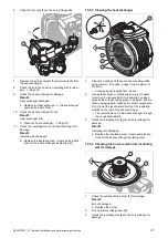
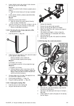
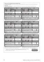
13.4.3 Replacing the gas valve assembly
Note
Each destroyed tamper-proof seal must be re-
placed with a new tamper-proof seal.
A
C
D
B
1.
Remove the gas valve assembly as shown in the fig-
ure.
2.
Install the new gas valve assembly in reverse order.
3.
Attach the two screws to the gas valve assembly.
–
Tightening torque: 2 Nm, if a torque spanner is
available
4.
When restarting the product, carry out a leak-tightness
test, check the CO
₂
content and, if required, adjust this.
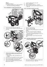
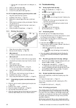
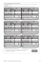
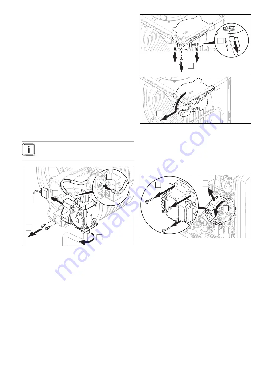
13.4.4 Replacing the fan
1.
Move the expansion vessel to the maintenance posi-
tion on the combustion block. (
2.
Remove the compact thermal module. (
x3
A
B
C
3.
Remove the fan as shown in the figure.
4.
Reinstall the new fan in the reverse order.
5.
Install the compact thermal module. (
6.
Reinstall the expansion vessel.
7.
When restarting the product, check the CO
₂
content
and, if required, adjust this.
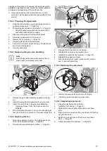
13.4.5 Replacing the pump head
x3
B
C
A
1.
Remove the pump head as shown in the figure.
2.
Install the new pump head in reverse order.
13.4.6 Completing repair work
1.
Hinge the electronics box upwards.
2.
Install the front casing. (
3.
Establish the power supply if this has not yet been
done.
4.
Open all service valves and the gas stopcock if this has
not yet been done.
5.
Switch the product back on if this has not yet been
done. (
6.
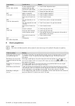
Check the product for tightness. (