


0020313973_01 Compact Installation and maintenance instructions
25
8.
To avoid short circuits resulting from loose individual
wires, fit conductor end sleeves on the stripped ends of
the conductors.
9.
Screw the respective plug to the connection cable.
10.
Check whether all conductors are inserted mechanic-
ally securely in the plug terminals. Remedy this if ne-
cessary.
11.
Plug the plug into the associated PCB slot.
Wiring diagram (
7.9.4
Establishing the power supply
1.
Provide one common power supply for the boiler and
for the corresponding control:
–
Power supply: single-phase, 230 V, 50 Hz
–
Fuse:
≤
3 A
2.
Ensure that the mains voltage is 230 V.
3.
Connect the product using a fixed connection and an
electrical partition with a contact gap of at least 3 mm
(e.g. fuses or power switches).
4.
Make sure that access to the power supply is always
available and is not covered or blocked.
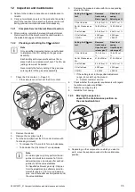
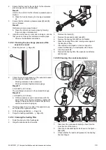
7.9.5
Connecting the control
Note
When connecting to an
eBUS
room thermostat
after starting up, establish the connection in or-
der to set the heating flow and domestic hot water
temperature on the product to the relevant max-
imum value.
BUS
24V
– +
24V=
RT
BUS
Burner
off
X106
X41
1
2
3
4
5
1
Limit thermostat for
underfloor heating
2
Control
24 V (ON/OFF)
3
eBUS
control or radio
receiver unit
4
Outdoor temperature
sensor, wired
5
eBUS
control or radio
receiver unit
1.
Ensure that the product is voltage-free.
2.
Carry out the wiring. (
3.
Alternatives 1
‒
Connecting the weather-
compensated control or room thermostat via
eBUS
:
▶
Connect the control to the
BUS
connection
(3)
or
(5)
.
▶
Bridge the
24 VRT
connection, if no bridge is
present.
3.
Alternatives 2
‒
Connecting the low-voltage
control (24 V):
▶
Remove the bridge and connect the control to the
24 V
=
RT
(2)
connection.
3.
Alternatives 3
‒
Connecting a limit thermostat
for underfloor heating:
▶
Remove the bridge and connect the limit thermostat
to the
Burner off
(1)
connection.