


11
Swiss Lifting Solutions
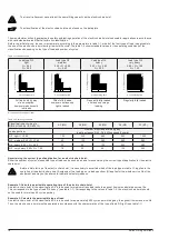
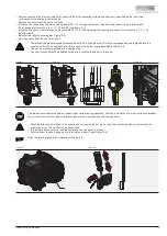
The electric chain hoist meets the requirements of the EC Machinery Directive and the harmonized EN standards. Housing and cover of
the electric chain hoist are made of a sturdy die-cast aluminium. Cooling fins and a fan on the attached motor ensure optimum cooling.
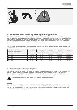
The chain container can be attached to the compactly constructed housing. A drilled hole is provided for the power supply cable gland
and for the cable gland for the control cable. The eyebolt suspension or optional hook suspension are attached on the housing.
GIS electric chain hoists are driven by asynchronous motors. Two-speed models include a pole-changeable version of the motor.
The braking system consists of one DC-operated magnetic brake. When there is no current, pressure springs generate the braking torque.
The slipping clutch is installed in front of of the braking system due to its function. It protects the chain hoist from overload and takes on
the function of an emergency stop for the highest and lowest hook positions. A geared limit switch is installed to limit the highest and
lowest hook position. Optionally, downstream forced disconnecting emergency stop contacts can be retrofitted.
The electric chain hoists are equipped with a 42 V contactor control as standard. The generally built-in emergency stop contactor
disconnects all three main phases from the mains when the red emergency stop button is pressed.
The high tensile profile steel chain corresponds to grade DAT (8SS) per DIN EN 818-7. The chain wheel is hardened. The load hook,
which complies with DIN 15401 / DIN EN 13001, is fitted with a safety catch. The 3-stage enclosed spur gears are generally helical.
The gears are mounted on roller bearings and run with grease lubrication.
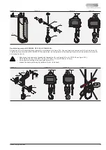
The standard equipment of the electric chain hoist includes a control switch (up/down with emergency stop). The special versions are
described in a separate instruction manual.
Control switch
Single fall
Double fall
1) Control unit box
2) Rotor shaft
3) Motor
4) Housing
5) Brake
6) Electrical control
7) Transmission
8) Limit switch
6
7
8
1
2
3
4
5
Figure 1-1
1.2 General description
Содержание GP 1000
Страница 1: ...06 20 Translation 9500 9002 1 TRANSLATION OF THE ORIGINAL INSTRUCTION MANUAL ELECTRIC CHAIN HOIST GP ...
Страница 2: ......
Страница 28: ......


