


Boomerang 12 user manual
_____________________________________________________________________________________________________________________________________
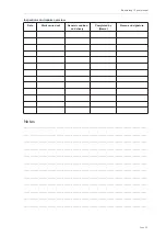
Riser lengths [mm] *
A
A’
Stabilo
B
Trim speed
520
485
505
520
Full speed
380
400
440
520
* incl. carabiner (Maillions)
The Boomerang 12 basic trim speed can be increased considerably by using the additional speed
system. It is particularly useful if there is a strong headwind, for valley crossings or to leave a
dangerous area quickly.
The speed system accelerates the wing by progressively shortening the risers towards the front.
This decreases the canopy’s original angle of attack and the speed of the glider increases.
The speed system must be correctly
fi
tted and adjusted to ensure it operates smoothly during
fl
ight.
Before
fi
rst launch, the length should be adjusted to suit the pilot and the line duct should be
checked.
The speed bar and the riser are connected by special Brummel hooks. Adjust the length to the
speed system so that your legs are fully stretched when at maximum accelerated
fl
ight
(“pulley-to-pulley” on the riser), otherwise you may experience symptoms of fatigue in long
fl
ights. You
should still be in a comfortable
fl
ight position even when the speed system is used to its full extent.
You will not be able to use the full potential of your paraglider if the speed system is too long.
Fasten the speed bar to the harness before launch to avoid tripping over it when preparing to launch
or taking off.
Line system and brakes
The Boomerang 12 has A and B line levels, which fork three or four times from the bottom (riser) to the
top (canopy) and which are divided into "Main", "Middle", "Higher-Middle" and "Top" lines. The
individual line levels are connected with one another using the “handshake knot”.
With the brake lines, the individual levels are bundled at the end with the main brake line. This runs
through the low friction ring attached to the riser and is knotted at the brake loop of the control
handle. There is a mark on the main brake line which allows the control handle to be correctly
positioned.
The main lines are all attached to Maillon quick links. They are fed through special elastic rings (or
plastic clips) and attached to prevent the lines from slipping and to ensure that they sit in the correct
position.
Page 38
Содержание Boomerang12
Страница 1: ...v1 0 March 2022...
Страница 46: ...www gingliders com...