HS-50 & HS-100
Doc. No 1199-PS-0035 Issue 3
June 2021
___________________________________________________________________________________________
Page 41
15 USING ANALOGUE OUTPUTS WITH PCIA BOX
(1189-PK-020).
15.1 Introduction
Analogue outputs can be provided by using the optional PCIA. The analogue output card decodes
the serial message from the anemometer and generates the appropriate analogue outputs. Seven
analogue outputs are provided of 14 bit resolution. The pin assignment for these is given in Section
10.1.4.
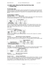
15.2 Analogue outputs
Channels 1,2 and 3
-
Wind velocity
These channels represent the wind velocity. The variables represented by each channel depend on
the anemometer's operating mode, and are defined in the following table:
Output Channel
Mode
1
2
3
UVW
U
V
W
Polar format
Dir.
Mag.
W
Axis velocities
Axis 1
Axis 2
Axis 3
For U, V and W m agnitude, and axis velocities, ±2.5V represents ±10, ±20, ±30 or
±60m /s as selected when configuring the anemometer. For direction in polar format the ±2.5V
output range represents either 360° or 540°. This option is also set up when configuring the
anemometer.
The direction representation is:
Output voltage (V)
-2.5
0.833
0
+0.833
+2.5
360°
-180°
0°
+180°
540°
0°
180°
360°
+540°
The 540° mode avoids the output oscillating between -2.5V and +2.5V in response to a direction
varying around 180°.
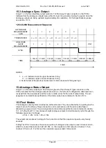
Channel 4
-
Speed of Sound or Sonic Temperature
The variable represented by this analogue output also depends on the configuration of the
anemometer's speed of sound or sonic temperature. The representations for each available mode
are:
Output voltage (V)
-2.5
-1.667
0
+2.5
Speed of Sound
300
311.67
335
370
Sonic temperature (Kelvin)
233.15
273.15
333.15
Sonic temperature (Celsius)
-40
0
+60
Channel 5
-
Absolute Temperature
The voltage output at a given temperature is independent of the anemometer's temperature output
configuration. The following table shows the mapping between voltage and temperature:
Output voltage (V)
-1.667
0
+2.5
Celsius
-40
0
+60
Kelvin
233.15
273.15
333.15
Channel 6
-
Reserved for future expansion
This analogue output is not currently used.
Channel 7 and 8 -
Analogue Inputs/Outputs
Channels 7 and 8 echo the voltage on the lowest two analogue inputs that are enabled i.e. the first
two in the serial data message from the anemometer. The analogue inputs at the anemometer are
in the range ±5V. The analogue outputs have a range of ±2.5V. The voltage output is half the
analogue input value. For example an analogue input of +5V is echoed at +2.5V.
Содержание 1199-PK-085
Страница 1: ......

