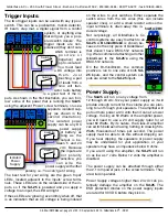
Trigger Inputs:
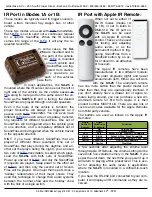
The two trigger inputs can be used with any type of
switch. This can be a pushbutton, motion detector,
IR beam, step mat, a digital signal from a control
system, or anything else
that will give you a
ʻ
pow-
ered switch closure
ʼ
. The
trigger inputs are non-
polarized (they don
ʼ
t care
which terminal is
p o s i t i v e o r
negative) and
opto-isolated.
You must feed
a DC voltage into
t h e m . J u s t
touching a pair
of leads from a
nine volt tran-
sistor radio battery
is a good test of the in-
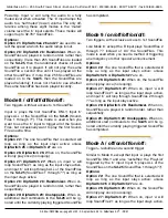
puts. As shown in the first illustration, you can
ʻ
bor-
row
ʼ
some of the power that is running the
Sd-25
using the adjacent
ʻ
Power
ʼ
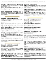
screw terminals, or use a
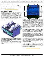
separate isolated sup-
ply (as shown in the
second illustration).
The isolated power
supply can be any DC
power supply
or battery, as
long as the
output is be-
tween 5 and 24
vdc. Because
the inputs are
n o t p o l a r i t y
sensitive, you
c a n w i r e t h e
power supply with either
polarity. i.e.: You can
ʼ
t get it wrong.
The best test for your wiring are the green
ʻ
Input
ʼ
LEDs, located adjacent to the inputs
ʼ
screw termi-
nals. These LEDs are on the isolated side of the in-
puts, so if the
Sd-25
is powered and you apply a
voltage to an input, the LED will light.
If these LEDs are
ʻ
glowing
ʼ
even dimly when off, that
is an indication that an AC voltage is being induced
B
Right
Power
12-24
vdc
A
Trigger
Inputs
Speakers
Running
Status
Switch 'B'
Switch 'A'
B
Left
Right
Power
12-24
vdc
A
Trigger
Inputs
Speakers
(8
Ω
)
Running
Status
Switch 'B'
Switch 'A'
Isolated
Power
Supply
on the wires to your switches. Either separate the
switch wires from the AC wires (this can include
speaker lines), or add a small resistor across the
input terminals to drain away this in-
duced voltage.
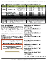
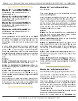
Not surprisingly, all Gilderfluke & Co.
control systems are easy to attach to an
Sd-25
. A
Br-miniBrick4
is shown be-
cause it is the only piece of GilderGear
that doesn't have DMX-512 network-
ing. We recommend attaching all other
GilderGear to the
Sd-25
ʼ
s
using the
DMX-512 network.
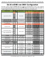
On the Br-miniBrick4, the common
positive is run to one side of both
Sd-
25
inputs, and the control system out-
puts are wired to the
Sd-25
inputs.
Power Supply:
The
Sd-25
will run on any voltage from
12 through 24 vdc. Size your power supply so it will
provide enough current for the volume you are plan-
ning to run through your speakers. The amplifier will
put out more power at 24 volts than it can at a lower
voltage. If using all 50 Watts of the amplifier power,
you will need to use a 24 volt supply rated for at
least 60 Watts. By its nature, the Class-D amplifier
can switch between drawing nothing to drawing 50+
Watts thousands of times per second. The power
supply must be able to do this without dropping out.
If you hear clipping, the speakers or power supply
may be undersized for your application, or your
speakers may have an impedance below 8 ohms.
If you aren
ʼ
t using the amplifier, the
Sd-25
will run
on as low as 7 volts. Below 12 volts the amplifier is
disabled.
The power supply can be attached through either
the 2.1 mm power jack, or the screw terminals. They
are wired in parallel.
Power Supply voltages higher than 24 vdc can po-
tentially damage the amplifier on the
Sd-25
. The
ESD protection diodes on the power supply inputs
are rated for 30 VDC before they kick in.
Br-MiniBrick4
Gilderfluke & Co.
Burbank, California
0 1
2 3
Record Go
Data
Trigger
9-24
vdc
Outputs
Outputs
Triggering from a
Control System
A
Inputs
B
Sd-10
Sd-25 w/DMX
Gilderfluke & Co.• 205 South Flower Street • Burbank, California 91502 • 818/840-9484 • 800/776-5972 • fax 818/840-9485
Sd-25 w/DMX Manual • page 14 of 32 • © September 4, 2014 • Gilderfluke & Co. • DCM


