background image

- 89 -

Unique Features

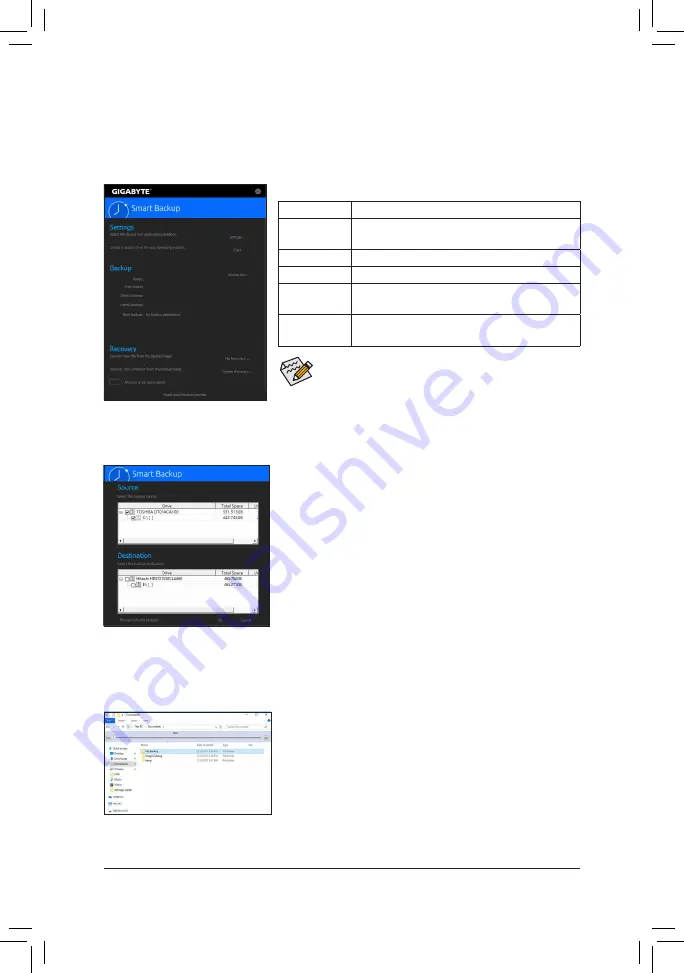
5-2-8  Smart Backup

Smart Backup allows you to back up a partition as an image file every hour. You can use these images to restore 
your system or files when needed.


Smart Backup only supports NTFS file system.


You need to select the destination partition in 

Settings

 the first time 

you use Smart Backup.


The 

Backup Now

 button will be available only after 10 minutes you 

have logged in Windows.


Select the 

Always run on next reboot

 checkbox to automatically 

enable Smart Backup after system reboot.

Creating a backup:

Click the 

Settings

 button on the main menu. In the 

Settings

 dialog 

box, select the source partition and destination partition and click 

OK

The initial backup will start after 10 minutes and regular backup will be 
performed hourly. Note: By default, all partitions on the system drive 
are selected as the backup source. The backup destination cannot be 
on the same partition as the backup source.

Saving the backup to a network location:

If you want to save the backup to a network location, select 

Browse 

network location

. Make sure your computer and the computer where 

you want to save the backup are in the same domain. Choose the 
network location where you want to store the backup and enter the user 
name and password. Follow the on-screen instructions to complete.

Recovering a file:

Click the 

File Recovery

 button on the main menu. Use the time slider on 

the top of the popped out window to select a previous backup time. The 
right pane will display the backed-up partitions in the backup destination 
(in the 

My Backup

 folder). Browse to the file you want and copy it.

The Smart Backup main menu:

Button

Description

Settings

Allows you to select the source and destination 

partition

Start

Allows you to create a rescue drive

Backup Now

Allows you to perform the backup immediately

File 

Recovery...

Allows you to recover your files from the backup 

image

System 

Recovery...

Allows you to recover your system from the 

backup image

Содержание TRX40 DESIGNARE

Страница 1: ...001 12ME TR4DES 1001R For more product details please visit GIGABYTE s website To reduce the impacts on global warming the packaging materials of this product are recyclable and reusable GIGABYTE works with you to protect the environment ...

Страница 2: ...Motherboard TRX40 DESIGNARE Nov 8 2019 Motherboard TRX40 DESIGNARE Nov 8 2019 Wireless Module Country Approvals ...

Страница 3: ... s prior written permission Documentation Classifications In order to assist in the use of this product GIGABYTE provides the following types of docu mentations For quick set up of the product read the Quick Installation Guide included with the product For detailed product information carefully read the User s Manual For product related information check on our website at https www gigabyte com Id...

Страница 4: ... 17 1 4 1 Quad Channel Memory Configuration 17 1 4 2 Installing a Memory 18 1 5 Installing an Expansion Card 19 1 6 Setting up AMD CrossFire NVIDIA SLI Configuration 20 1 7 Back Panel Connectors 21 1 8 Onboard LEDs and Buttons 23 1 9 Internal Connectors 24 Chapter 2 BIOS Setup 37 2 1 Startup Screen 38 2 2 The Main Menu 39 2 3 Favorites F11 41 2 4 Tweaker 42 2 5 Settings 46 2 6 System Info 55 2 7 B...

Страница 5: ...3 5 2 4 Fast Boot 84 5 2 5 Game Boost 85 5 2 6 RGB Fusion 86 5 2 7 Smart Keyboard 88 5 2 8 Smart Backup 89 5 2 9 System Information Viewer 91 5 2 10 Smart Survey 92 5 2 11 USB Blocker 93 5 2 12 USB TurboCharger 94 Chapter 6 Appendix 95 6 1 Configuring Audio Input and Output 95 6 1 1 Configuring 2 4 5 1 7 1 Channel Audio 95 6 1 2 Configuring S PDIF Out 97 6 1 3 Using the Voice Recorder 97 6 1 4 DTS...

Страница 6: ...rip adapter cable 5 5 One RGB LED strip extension cable 5 5 Two thermistor cables 5 5 One G Connector 5 5 M 2 screw s M 2 standoff s Optional Items 2 port USB 2 0 bracket Part No 12CR1 1UB030 6 R eSATA bracket Part No 12CF1 3SATPW 4 R 3 5 Front Panel with 2 USB 3 2 Gen 1 ports Part No 12CR1 FPX582 2 R The box contents above are for reference only and the actual items shall depend on the product pa...

Страница 7: ...IEX8_1 PCIEX1 PCIEX16_2 PCIEX8_2 CPU_OPT DDR4_D2 DDR4_A1 DDR4_D1 DDR4_A2 DDR4_C2 DDR4_B1 DDR4_C1 DDR4_B2 TRX40 DESIGNARE F_PANEL SYS_FAN5A_ PUMP F_USB32_1 F_USB32_2 F_USB20_1 D_LED1 TPM SYS_FAN2 F_U32C SYS_FAN5B_PUMP F_USB20_2 F_AUDIO LED_C1 iTE Super I O THB_C SATA3 6 4 2 0 7 5 3 1 M2M 60 80 110 M2Q 80 CODEC ALC4050H SYS_FAN1 USB 2 0 Hub USB 2 0 Hub VGA DRAM CPU BOOT Note For debug code informati...

Страница 8: ... 3 M2M M2Q SPI Bus Dual BIOS LPC Bus TPM iTE Super I O AMD Socket sTRX4 CPU 4 USB 3 2 Gen 2 x1 x1 x1 x1 8 SATA 6Gb s SATA3 0 7 4 USB 3 2 Gen 1 LAN1 RJ45 Intel GbE LAN LAN2 RJ45 Intel GbE LAN PCI Express 4 0 Bus Center Subwoofer Speaker Out Line Out MIC Line In S PDIF Out Rear Speaker Out Realtek ALC4050H CODEC AMD TRX40 2 M 2 Socket 3 M2P M2C 2 USB Type C with USB 3 2 Gen 2 support 1 USB 3 2 Gen 2...

Страница 9: ...d first touch a metal object to eliminate static electricity Prior to installing the motherboard please have it on top of an antistatic pad or within an electrostatic shielding container Before connecting or unplugging the power supply cable from the motherboard make sure the power supply has been turned off Before turning on the power make sure the power supply voltage has been set according to t...

Страница 10: ...ule Intel Wi Fi 6 AX200 Wi Fi 802 11a b g n ac ax supporting 2 4 5 GHz Dual Band BLUETOOTH 5 0 Support for 11ax 160MHz wireless standard and up to 2 4 Gbps data rate Actual data rate may vary depending on environment and equipment Expansion Slots 2 x PCI Express x16 slots running at x16 PCIEX16_1 PCIEX16_2 2 x PCI Express x16 slots running at x8 PCIEX8_1 PCIEX8_2 1 x PCI Express x1 slot All of the...

Страница 11: ...der 2 x system fan headers 4 x system fan water cooling pump headers 2 x addressable LED strip headers 2 x RGB LED strip headers 4 x M 2 Socket 3 connectors 8 x SATA 6Gb s connectors 1 x front panel header 1 x front panel audio header 1 x USB Type C header with USB 3 2 Gen 2 support 2 x USB 3 2 Gen 1 headers 2 x USB 2 0 1 1 headers 1 x GIGABYTE GC TITAN RIDGE Add in Card Connector 1 x Trusted Plat...

Страница 12: ...oard specifications BIOS AutoGreen Cloud Station EasyTune Fast Boot Game Boost RGB Fusion Smart Backup Smart Keyboard Smart Survey System Information Viewer USB Blocker USB TurboCharger Support for Q Flash Plus Support for Q Flash Support for Xpress Install Bundled Software Norton Internet Security OEM version XSplit Gamecaster Broadcaster 12 months license cFosSpeed Operating System Support for W...

Страница 13: ...t hardware damage Apply an even and thin layer of thermal grease on the surface of the CPU Do not turn on the computer if the CPU cooler is not installed otherwise overheating and damage of the CPU may occur Set the CPU host frequency in accordance with the CPU specifications It is not recommended that the system bus frequency be set beyond hardware specifications since it does not meet the standa...

Страница 14: ...e loosenthescrews in 3 2 1 sequence ToclosetheCPUmetalloadplate tightenthescrews in 1 2 3 sequence Step 2 ToopentheCPUmetalloadplate startbyloosening Screw 3 then Screw 2 and finally Screw 1 After all three screws are loosened gently lift the load plate to its fully open position Screw 3 Screw 2 Screw 1 Step 4 Use one hand to hold the rail frame and the other to slide the external cap out of the r...

Страница 15: ...ressing down on the load plate begin tightening Screw 1 slightly Then do the same to Screw 2 and Screw 3 Next fully tighten the three screws Make sure the motherboard is placed on a stable surface during the tightening process Step 6 Push the carrier frame into place and you will hear a click sound when it is pushed to the bottom Warning The CPU carrier frame cannot be placed outside the rails Ste...

Страница 16: ...cooler may damage the CPU Step 1 Apply an even and thin layer of thermal grease on the surface of the installed CPU Step 2 Place the cooler atop the CPU aligning the four mounting screws with the mounting holes around the CPU socket NOTE the spacing between the upper two screws is not the same as that between the lower two screws please make sure to align the screws correctly CPU Cooler Mounting H...

Страница 17: ...the memory is installed the BIOS will automatically detect the specifications and capacity of the memory The eight DDR4 memory sockets are divided into four channels and each channel has two memory sockets as following Channel A DDR4_A1 DDR4_A2 Channel B DDR4_B1 DDR4_B2 Channel C DDR4_C1 DDR4_C2 Channel D DDR4_D1 DDR4_D2 DDR4_D2 DDR4_A1 DDR4_C2 DDR4_B1 DDR4_D1 DDR4_A2 DDR4_C1 DDR4_B2 Refer to the ...

Страница 18: ...o it can only fit in one direction Follow the steps below to correctly install your memory modules in the memory sockets Notch DDR4 DIMM Step 1 Note the orientation of the memory module Spread the retaining clip at the right end of the memory socket Place the memory module on the socket As indicated in the picture on the left place your fingers on the top edge of the memory push down on the memory...

Страница 19: ...sion card s 7 Install the driver provided with the expansion card in your operating system Example Installing and Removing a PCI Express Graphics Card PCI Express x16 Slot Installing a Graphics Card Gently push down on the top edge of the card until it is fully inserted into the PCI Express slot Make sure the card is securely seated in the slot and does not rock Removing the Card Gently push back ...

Страница 20: ...hics cards for the power requirement B Connecting the Graphics Cards Step 1 Observe the steps in 1 5 Installing an Expansion Card and install CrossFire SLI graphics cards on the PCI Express x16 slots Step 2 Insert the CrossFire Note 2 SLI bridge connectors in the CrossFire SLI gold edge connectors on top of the cards Step 3 Plug the display cable into the graphics card on the PCIEX16_1 slot Proced...

Страница 21: ...The Gigabit Ethernet LAN port provides Internet connection at up to 1 Gbps data rate The following describes the states of the LAN port LEDs Always turn off your computer and unplug the power cord from the power outlet before using the clear CMOS button Do not use the clear CMOS button when the system is on or the system may shutdown and data loss or damage may occur After system restart go to BIO...

Страница 22: ...de Speaker Out The line in jack Use this audio jack for line in devices such as an optical drive walkman etc Line Out Front Speaker Out The line out jack Mic In The Mic in jack Audio Jack Configurations Jack Headphone 2 channel 4 channel 5 1 channel 7 1 channel Center Subwoofer Speaker Out a a Rear Speaker Out a a a Line In Side Speaker Out a Line Out Front Speaker Out a a a a Mic In a If you want...

Страница 23: ... that means you haven t entered the operating system yet VGA Graphics card status LED DRAM Memory status LED CPU CPU status LED BOOT Operating system status LED Quick Button This motherboard has 2 quick buttons power button and reset button The power button and reset button allow users to quickly turn on off or reset the computer in an open case environment when they want to change hardware compon...

Страница 24: ...devices After installing the device and before turning on the computer make sure the device cable has been securely attached to the connector on the motherboard 1 ATX_12V1 ATX_12V2 2 ATX 3 OC_PEG 4 CPU_FAN 5 SYS_FAN1 2 6 SYS_FAN5A B_PUMP SYS_FAN6A B_PUMP 7 CPU_OPT 8 EC_TEMP1 EC_TEMP2 9 D_LED1 D_LED2 10 LED_C1 LED_C2 11 SATA3 0 1 2 3 4 5 6 7 12 M2M M2Q M2P M2C 13 F_PANEL 14 F_AUDIO 15 F_U32C 16 F_U...

Страница 25: ... computer will not start 13 1 24 12 ATX 8 4 5 1 ATX_12V1 ATX_12V2 Pin No Definition 1 GND Only for 2x4 pin 12V 2 GND Only for 2x4 pin 12V 3 GND 4 GND 5 12V Only for 2x4 pin 12V 6 12V Only for 2x4 pin 12V 7 12V 8 12V ATX Pin No Definition Pin No Definition 1 3 3V 13 3 3V 2 3 3V 14 12V 3 GND 15 GND 4 5V 16 PS_ON soft On Off 5 GND 17 GND 6 5V 18 GND 7 GND 19 GND 8 Power Good 20 NC 9 5VSB stand by 5V ...

Страница 26: ...onboard PCI Express x16 slots When two or more graphics cards are installed we recommend that you connect the power cable from the power supply to the ATX4P connector to ensure system stability Pin No Definition 1 GND 2 Voltage Speed Control 3 Sense 4 PWM Speed Control Pin No Definition 1 12V 2 12V 3 12V 4 GND 5 GND 6 GND CPU_FAN 1 1 1 SYS_FAN2 SYS_FAN1 Be sure to connect fan cables to the fan hea...

Страница 27: ...tion Pin No Definition 1 GND 2 Voltage Speed Control 3 Sense 4 PWM Speed Control 1 1 SYS_FAN5A B_PUMP SYS_FAN6A B_PUMP 7 CPU_OPT Water Cooling CPU Fan Header The fan header is 4 pin and possesses a foolproof insertion design Most fan headers possess a foolproof insertion design When connecting a fan cable be sure to connect it in the correct orientation the black connector wire is the ground wire ...

Страница 28: ...and the other end to your addressable LED strip The power pin marked with a triangle on the plug of the LED strip must be connected to Pin 1 of the addressable LED strip header Incorrect connection may lead to the damage of the LED strip Addressable LED Strip Adapter Cable 1 Before installing the devices be sure to turn off the devices and your computer Unplug the power cord from the power outlet ...

Страница 29: ...rrect connection may lead to the damage of the LED strip 12V R G B B G 12V R 12V 1 RGB LED Strip 12V R G B B G 12V R 1 LED_C2 1 LED_C1 DEBUG PORT DEBUG PORT Pin No Definition 1 12V 2 G 3 R 4 B 11 SATA3 0 1 2 3 4 5 6 7 SATA 6Gb s Connectors TheSATAconnectorsconformtoSATA6Gb sstandardandarecompatiblewithSATA3Gb sandSATA1 5Gb s standard Each SATAconnector supports a single SATAdevice TheAMD Chipset s...

Страница 30: ...be installed and then tighten the standoff first Insert the M 2 SSD into the M 2 connector at an angle 12 M2M M2Q M2P M2C M 2 Socket 3 Connectors The M 2 connectors support M 2 SATA SSDs or M 2 PCIe SSDs and support RAID configuration Please note that an M 2 PCIe SSD cannot be used to create a RAID set either with an M 2 SATA SSD or a SATA hard drive Refer to Chapter 3 Configuring a RAID Set for i...

Страница 31: ...reset switch on the chassis front panel Press the reset switch to restart the computer if the computer freezes and fails to perform a normal restart CI Chassis Intrusion Header Connects to the chassis intrusion switch sensor on the chassis that can detect if the chassis cover has been removed This function requires a chassis with a chassis intrusion switch sensor NC No connection PLED PWR_LED Powe...

Страница 32: ... S _ S F B_ _ _ _ _B S _S _ S _ 9 1 10 2 Some chassis provide a front panel audio module that has separated connectors on each wire instead of a single plug For information about connecting the front panel audio module that has different wire assignments please contact the chassis manufacturer 15 F_U32C USB Type C Header with USB 3 2 Gen 2 Support The header conforms to USB 3 2 Gen 2 specification...

Страница 33: ...B ports via an optional USB bracket For purchasing the optional USB bracket please contact the local dealer Pin No Definition 1 Power 5V 2 Power 5V 3 USB DX 4 USB DY 5 USB DX 6 USB DY 7 GND 8 GND 9 No Pin 10 NC EBUG ORT G QBOFM 10 9 2 1 Do not plug the IEEE 1394 bracket 2x5 pin cable into the USB 2 0 1 1 header Prior to installing the USB bracket be sure to turn off your computer and unplug the po...

Страница 34: ... 5V 3A quick power charge support _ B_ USB 0_ B B_ F_USB3 F_USB30 3 1 _ B B S_ B S B_ B _ S S_ _ B _ U _ B 1 2 3 1 2 3 1 2 3 1 2 3 1 1 1 1 B S S S _S U _ _ 3 F_USB3 F F _ 0 _ 0 F _ F _ _ _ _B _S _ S F_ B _ _3 U S _ Pin No Definition 1 LAD0 2 VCC3 3 LAD1 4 No Pin 5 LAD2 6 LCLK 7 LAD3 8 GND 9 LFRAME 10 NC 11 SERIRQ 12 LRESET 12 11 2 1 19 TPM Trusted Platform Module Header You may connect a TPM Trust...

Страница 35: ...ivalent one Damage to your devices may occur if the battery is replaced with an incorrect model Contact the place of purchase or local dealer if you are not able to replace the battery by yourself or uncertain about the battery model When installing the battery note the orientation of the positive side and the negative side of the battery the positive side should face up Used batteries must be han...

Страница 36: ... 36 Hardware Installation ...

Страница 37: ...ithout entering the operating system BIOS is a Windows based utility that searches and downloads the latest version of BIOS from the Internet and updates the BIOS For instructions on using the Q Flash and BIOS utilities refer to Chapter 5 BIOS Update Utilities Chapter 2 BIOS Setup Because BIOS flashing is potentially risky if you do not encounter problems using the current version of BIOS it is re...

Страница 38: ...t boot device without entering BIOS Setup In Boot Menu use the up arrow key h or the down arrow key i to select the first boot device then press Enter to accept The system will boot from the device immediately Note The setting in Boot Menu is effective for one time only After system restart the device boot order will still be based on BIOS Setup settings END Q FLASH Press the End key to access the...

Страница 39: ... the numeric value or make changes Page Down Decrease the numeric value or make changes F1 Show descriptions of the function keys F2 Switch to Easy Mode F3 Save the current BIOS settings to a profile F4 Load the BIOS settings from a profile created before F5 Restore the previous BIOS settings for the current submenus F6 Display the Smart Fan 5 screen F7 Load the Optimized BIOS default settings for...

Страница 40: ...ode allows users to quickly view their current system information or to make adjustments for optimum performance In Easy Mode you can use your mouse to move through configuration items or press F2 to switch to the Advanced Mode screen ...

Страница 41: ...s as your favorites and use the F11 key to quickly switch to the page where all of your favorite options are located To add or remove a favorite option go to its original page and press Insert on the option The option is marked with a star sign if set as a favorite ...

Страница 42: ...on the CPU being installed Whether the system will work stably with the overclock overvoltage settings you made is dependent on your overall system configurations Incorrectly doing overclock overvoltage may result in damage to CPU chipset or memory and reduce the useful life of these components This page is for advanced users only and we recommend you not to alter the default settings to prevent s...

Страница 43: ...figure this setting Default CCD Control Sets the number of CCDs to be used Default Auto Downcore Control Allows you to select the number of CPU cores to enable the number of CPU cores may vary by CPU Default Auto SMT Mode Allows you to enable or disable the CPU Simultaneous Multi Threading technology Default Auto Extreme Memory Profile X M P Note Allows the BIOS to read the SPD data on XMP memory ...

Страница 44: ...changes on the memory timings If this occurs please reset the board to default values by loading optimized defaults or clearing the CMOS values SPD Info Displays information on the installed memory CPU Vcore Dynamic Vcore DVID VCORE SOC Dynamic VCORE SOC DVID CPU VDD18 PCH_CLDO PM_1VSOC PM_1V8 DRAM Voltage CH A B DDRVPP Voltage CH A B DRAM Termination CH A B DRAM Voltage CH C D DDRVPP Voltage CH C...

Страница 45: ...BIOS Setup 45 CPU VRM Settings This submenu allows you to configure Load Line Calibration level over voltage protection level over current protection level and PWM phases ...

Страница 46: ...m consume least power in S5 shutdown state Default Disabled Note When this item is set to Enabled the following functions will become unavailable Resume byAlarm power on by mouse and power on by keyboard Soft Off by PWR BTTN Configures the way to turn off the computer in MS DOS mode using the power button Instant Off Press the power button and then the system will be turned off instantly Default D...

Страница 47: ... on LAN Enables or disables the wake on LAN function Default Enabled Initial Display Output Specifies the first initiation of the monitor display from the onboard graphics or the installed PCI Express graphics card PCIe 1 Slot Sets the graphics card on the PCIEX16_1 slot as the first display Default PCIe 2 Slot Sets the graphics card on the PCIEX8_1 slot as the first display PCIe 3 Slot Sets the g...

Страница 48: ...used in MS DOS Default Enabled XHCI Hand off Determines whether to enable XHCI Hand off feature for an operating system without XHCI Hand off support Default Enabled USB Mass Storage Driver Support Enables or disables support for USB storage devices Default Enabled Port 60 64 Emulation Enables or disables emulation of I O ports 64h and 60h This should be enabled for full legacy support for USB key...

Страница 49: ...tem is configurable only when Network Stack is enabled Ipv6 PXE Support Enables or disables IPv6 PXE Support This item is configurable only when Network Stack is enabled Ipv6 HTTP Support Enables or disables HTTP boot support for IPv6 This item is configurable only when Network Stack is enabled IPSEC Certificate Enables or disables the Internet Protocol Security This item is configurable only when...

Страница 50: ... enable or disable the LED lighting of the Clear CMOS button and power button when the system is on Default On Onboard Debug Port LED Allows you to enable or disable the LED lighting of the motherboard debug LEDs when the system is on Default On PCIe Slot Configuration Allows you to set the operation mode of the PCI Express slots to Gen 1 Gen 2 Gen 3 or Gen 4 Actual operation mode is subject to th...

Страница 51: ...BIOS Setup 51 This sub menu provides AMD CBS related configuration options AMD CBS ...

Страница 52: ... detection device attached to the motherboard CI header If the system chassis cover is removed this field will show Yes otherwise it will show No To clear the chassis intrusion status record set Reset Case Open Status to Enabled save the settings to the CMOS and then restart your system CPU Vcore CPU VCORE SOC CPU VDD18 DRAM Channel A B Voltage DRAM Channel C D Voltage DDRVPP Channel A B Voltage D...

Страница 53: ...the temperature interval for fan speed change Fan Pump Control mode Auto Lets the BIOS automatically detect the type of fan pump installed and sets the optimal control mode Default Voltage Voltage mode is recommended for a 3 pin fan pump PWM PWM mode is recommended for a 4 pin fan pump Fan Pump Stop Enables or disables the fan pump stop function You can set the temperature limit using the temperat...

Страница 54: ...he threshold BIOS will emit warning sound Options are Disabled default 60o C 140o F 70o C 158o F 80o C 176o F 90o C 194o F Fan Pump Fail Warning Allows the system to emit warning sound if the fan pump is not connected or fails Check the fan pump condition or fan pump connection when this occurs Default Disabled ...

Страница 55: ... format is hour minute and second For example 1 p m is 13 00 00 Use Enter to switch between the Hour Minute and Second fields and use the Page Up or Page Down key to set the desired value Access Level Displays the current access level depending on the type of password protection used If no password is set the default will display as Administrator The Administrator level allows you to make changes ...

Страница 56: ...assword s under the Administrator Password User Password item Setup A password is only required for entering the BIOS Setup program System A password is required for booting the system and for entering the BIOS Setup program Default Full Screen LOGO Show Allows you to determine whether to display the GIGABYTE Logo at system startup Disabled skips the GIGABYTE Logo when the system starts up Default...

Страница 57: ...able the legacy option ROM for the LAN controller Default Disabled This item is configurable only when CSM Support is set to Enabled Storage Boot Option Control Allows you to select whether to enable the UEFI or legacy option ROM for the storage device controller Disabled Disables option ROM UEFI Only Enables UEFI option ROM only Default Legacy Only Enables legacy option ROM only This item is conf...

Страница 58: ...sword press Enter on the password item and when requested for the password enter the correct one first When prompted for a new password press Enter without entering any password Press Enter again when prompted to confirm NOTE Before setting the User Password be sure to set the Administrator Password first Secure Boot Allows you to enable or disable Secure Boot and configure related settings This i...

Страница 59: ...nter on the device you select and select Yes to confirm Your system will restart automatically and boot from that device Save Profiles This function allows you to save the current BIOS settings to a profile You can create up to 8 profiles and save as Setup Profile 1 Setup Profile 8 Press Enter to complete Or you can select Select File in HDD FDD USB to save the profile to your storage device Load ...

Страница 60: ...BIOS Setup 60 ...

Страница 61: ...talling SATA hard drive s in your computer Install the hard drives SSDs in the SATA M 2 connectors on the motherboard Then connect the power connectors from your power supply to the hard drives RAID Levels RAID 0 RAID 1 RAID 10 Minimum Number of Hard Drives 2 2 4 Array Capacity Number of hard drives Size of the smallest drive Size of the smallest drive Number of hard drives 2 Size of the smallest ...

Страница 62: ... Step Turn on your computer and press Delete to enter BIOS Setup during the POST Power On Self Test Under Settings IO Ports set SATAConfiguration SATAMode to RAID Figure 1 Then save the settings and restart your computer If you want to use NVMe PCIe SSDs to configure RAID make sure to set NVMe RAID mode to Enabled Then set how the bandwidth of the PCIe slot you use is divided Save the changes and ...

Страница 63: ...e RAIDXpert2 Configuration Utility screen press Enter on Array Management to enter the Create Array screen Then select a RAID level Figure 4 RAID levels supported include RAID 0 RAID 1 and RAID 10 the selections available depend on the number of the hard drives being installed Next press Enter on Select Physical Disks to enter the Select Physical Disks screen Figure 3 Figure 4 ...

Страница 64: ...y and set them to Enabled Next use the down arrow key to move to Apply Changes and press Enter Figure 5 Then return to the previous screen and set the Array Size Array Size Unit Read Cache Policy and Write Cache Policy Step 5 After setting the capacity move to Create Array and press Enter to begin Figure 6 Figure 5 Figure 6 ...

Страница 65: ...lume and information on RAID level array name array capacity etc Figure 7 Delete RAID Volume To delete a RAID array select the array to be deleted on the RAIDXpert2 Configuration Utility Array Management Delete Array screen Press Enter on Delete Array to enter the Delete screen Then set Confirm to Enabled and press Enter on Yes Figure 8 Figure 7 Figure 8 ...

Страница 66: ...installed requires that you provide additional SATA RAID AHCI driver during the OS installation process please refer to the steps below Step 1 Copy the Hw10 folder under the BootDrv folder in the driver disk to your USB thumb drive Step 2 Boot from the Windows setup disk and perform standard OS installation steps When the screen requesting you to load the driver appears select Browse Step 3 Insert...

Страница 67: ...hipset and RAID drivers have been installed from the motherboard driver disk Then double click the RAIDXpert2 icon on the desktop to launch the RAID utility Step 1 Enter the login ID and password default admin and then click Submit to launch AMD RAIDXpert2 Step 2 In the Disk Devices section left click your mouse twice on the newly added hard drive Step 3 On the next screen select Assign as Global ...

Страница 68: ... 68 Configuring a RAID Set ...

Страница 69: ...program Please ignore the popup dialog box es e g the Found New Hardware Wizard displayed when Xpress Install is installing the drivers Failure to do so may affect the driver installation Some device drivers will restart your system automatically during the driver installation After the system restart Xpress Install will continue to install other drivers Xpress Install will automatically scan your...

Страница 70: ...the GIGABYTE Taiwan headquarter You can click the URL on this page to link to the GIGABYTE website to check more information on the GIGABYTE headquarter or worldwide branch offices 4 2 Application Software This page displays the apps that GIGABYTE develops and some free software You can select the apps you want and click the Install icon to begin the installation ...

Страница 71: ... BIOS are easy to use and allow you to update the BIOS without the need to enter MS DOS mode Additionally this motherboard features the DualBIOS design and supports Q Flash Plus providing multiple protection for the safety and stability of your computer What is DualBIOS Motherboards that support DualBIOS have two BIOS onboard a main BIOS and a backup BIOS Normally the system works on the main BIOS...

Страница 72: ...B flash drive Step 1 1 Insert the USB flash drive containing the BIOS file into the computer In the main screen of Q Flash select Update BIOS The Save BIOS option allows you to save the current BIOS file Q Flash only supports USB flash drive or hard drives using FAT32 16 12 file system If the BIOS update file is saved to a hard drive in RAID AHCI mode or a hard drive attached to an independent SAT...

Страница 73: ...g the BIOS Do not remove the USB flash drive or hard drive when the system is updating the BIOS Step 4 During the POST press Delete to enter BIOS Setup Select Load Optimized Defaults on the Save Exit screen and press Enter to load BIOS defaults System will re detect all peripheral devices after a BIOS update so we recommend that you reload BIOS defaults Step 5 Select Save Exit Setup and press Ente...

Страница 74: ...te file for your motherboard is not present on the BIOS server site please manually download the BIOS update file from GIGABYTE s website and follow the instructions in Update the BIOS without Using the Internet Update Function below Supported image formats include jpg bmp and gif C After Updating the BIOS Restart your system after updating the BIOS 1 Update the BIOS Using the Internet Update Func...

Страница 75: ...system will automatically search and match the BIOS file in the USB flash drive on the Q Flash Plus port The Q Flash Plus button will flash during the BIOS matching and flashing process Wait for 2 3 minutes and the button will stop flashing when the BIOS flashing is complete Before using the Q Flash Plus function make sure that your system is off S5 shutdown state If your motherboard has a BIOS sw...

Страница 76: ...to Application Software Install GIGABYTE Utilities to install GIGABYTE App Center and the selected apps Restart your computer after the installation is complete In Desktop mode click the App Center icon in the notification area to launch the App Center utility Figure 1 On the main menu you can select an app to run or click LiveUpdate to update an app online If the App Center is closed you can rest...

Страница 77: ...he Bluetooth receiver on your computer Press Refresh to let AutoGreen search for the Bluetooth devices around you A message will appear on both your computer and smart phone tablet device prompting you to compare the passcodes on the two devices Confirm to complete the pairing process 5 2 1 AutoGreen AutoGreen Note is an easy to use tool that provides users with simple options to enable system pow...

Страница 78: ...meCloud files between computers you need to install Cloud Station Server on the host computer and Cloud Station on the remote computer Your smart phone tablet device must have Android 4 0 iOS 6 0 or above version The first time you use HomeCloud GIGABYTE Remote and Remote OC you must sign in with your Google Facebook Windows Live account Be sure to use the same account to sign in on your smart pho...

Страница 79: ...he files and select the files that you want to download to your smart phone tablet device All Music Files All Video Files All Files User Contacts Tap on the folder and then tap on the menu icon to use the options including Backup to remote Restore From remote View Remote Contact and Reselect Computers Call Log Using HomeCloud Step 1 Launch HomeCloud on the host computer installed with Cloud Statio...

Страница 80: ... next reboot Step 2 Run GIGABYTE Cloud Station on your smart phone tablet device sign in with the same account you use for HomeCloud on your computer Tap on Remote Control to perform the following remote controls On the Smart Phone Tablet Device Option Function Mouse Remotely perform mouse functionalities including dragging right left clicking and holding the mouse left button Keyboard Remotely co...

Страница 81: ...next reboot Step 2 Run GIGABYTE Cloud Station on your smart phone tablet device sign in with the same account you use for HomeCloud on your computer Tap on Remote OC to perform the following functions On the Smart Phone Tablet Device Option Function Tuner Allows you to change CPU memory frequency and voltage settings INFO Displays the system information including the CPU motherboard and memory HW ...

Страница 82: ...re are more than one Wi Fi card on your computer you need to select the one you want to use from the list SSID The hotspot SSID name You can keep the default name or create your own one HotSpot Password must have at least 8 characters The password is required when other wireless devices want to access the Internet through the virtual wireless access point You can keep the default name or create yo...

Страница 83: ...graphics frequency You can save the current settings to a profile You can create up to 2 profiles The Advanced DDR OC tab allows you to set the memory clock The Advanced Power tab allows you to adjust voltages The HotKey tab allows you to set hotkeys for your profiles Incorrectly doing overclock overvoltage may result in damage to the hardware components such as CPU chipset and memory and reduce t...

Страница 84: ...ion is the same as the Fast Boot option Note in BIOS Setup It allows you to enable or disable the fast boot function to shorten OS boot time After you configure the settings click Save to save and click Exit The settings will take effect on next boot If you click the Enter BIOS Setup Now button the system will restart and enter BIOS Setup immediately Note For more details about this function refer...

Страница 85: ...e Using Game Boost Select the application you want to suspend and then click Go to optimize your system for gaming To revert the computer back to the state it was before click Revert In addition two hotkeys are provided as follows Optimize Ctrl Alt B Automatically optimizes your gaming platform and gaming performance Revert Ctrl Alt R Restores your computer back to the state before the gaming begi...

Страница 86: ...rightsectionofthescreen Static All LEDs emit a single color Pulse All LEDs simultaneously fade in and fade out Flash All LEDs simultaneously flash on and off Double Flash All LEDs flash in an interlaced pattern Color Cycle All LEDs simultaneously cycle through a full spectrum of colors Music All LEDs are synchronized with your music Random Single LED regions flash randomly Wave A full color spectr...

Страница 87: ...e selected region LEDs simultaneously fade in and fade out Flash The selected region LEDs simultaneously flash on and off Double Flash All LEDs flash in an interlaced pattern Color Cycle All LEDs simultaneously cycle through a full spectrum of colors Digital Wave A full color spectrum cascades throughout the armor LED Digital A I Mode Provides multiple digital lighting mode throughout the armor LE...

Страница 88: ...y to record mouse location or set time interval between each keystroke Sniper Key Using this option you can switch the mouse sensitivity when you are in sniper mode for better sniper accuracy Smart Cut Allows you to create keyboard shortcuts for a file or an application Smart Key Allows you to give the selected key the ability to replace to a word or password Disable Allows you to disable the func...

Страница 89: ...annot be on the same partition as the backup source Saving the backup to a network location If you want to save the backup to a network location select Browse network location Make sure your computer and the computer where you want to save the backup are in the same domain Choose the network location where you want to store the backup and enter the user name and password Follow the on screen instr...

Страница 90: ...p created on the selected time point and click Restore 5 Confirm whether to restart your system to proceed with the restore immediately or later Once you respond Yes the system will restart to the Windows recovery environment Follow the onscreen instructions to restore your system All of your files and programs will be deleted and replaced with those on the selected backup If needed be sure to mak...

Страница 91: ...t the fan s workload according system temperatures or you can fix the fan speeds using the RPM Fixed Mode option Click the Calibrate button and the fan speed will be shown in relation to overall fan workload after calibration The Reset button can revert the fan settings back to the last saved values The System Alert tab allows you to monitor hardware temperature voltage and fan speed and set tempe...

Страница 92: ... used to help us understand how well our products perform over time to detect issues and to identify potential product improvements The Smart Survey Interface Using Smart Survey Clicking Here Allows you to check the complete list of collected data Sending Device Data to GIGABYTE Selecting I Agree means you consent to GIGABYTE s collection of your device data Smart Survey will not collect any data ...

Страница 93: ...USB device types on your PC Devices classes that are blocked will be ignored by the operating system The USB Blocker Interface Using USB Blocker Select the class of USB device that you would like to block or unblock Double left click to change the Blocked or Unblocked status and click OK Then enter your password and click OK to complete ...

Страница 94: ...mum output power of 10 W a Provides maximum output power of 18 W Apple Fast Charge Note 3 a Provides maximum output power of 15 W r a Supports quick charge r Not support quick charge While the system is in S3 S4 the Quick Charge and Apple Fast Charge modes can only deliver 5V standby power and the two front USB ports together can provide a total power of up to 10 W and do not support PME Event Wak...

Страница 95: ...k panel which support 2 4 5 1 7 1 channel audio The picture to the right shows the default audio jack assignments Center Subwoofer Speaker Out Line In Rear Speaker Out Front Speaker Out Mic In Step 2 OntheSpeakersscreen clicktheSpeakerConfiguration tab In the Speaker Configuration list select Stereo Quadraphonic 5 1 Speaker or 7 1 Speaker according to the type of speaker configuration you wish to ...

Страница 96: ...e notification area and right click on the icon Select Open Sound settings Step 2 Select Sound Control Panel Step 3 On the Playback tab make sure your headphone is set as the default playback device For the device connected to the Line out jack on the back panel right click on Speakers and select Set as Default Device for the device connected to the Line out jack on the front panel right click on ...

Страница 97: ...put screen select the sample rate and bit depth in the Default Format section 6 1 3 Using the Voice Recorder A Recording Audio 1 To begin the recording click the Record icon 2 To stop the recording click the Stop recording icon B Playing the Recorded Sound The recordings will saved in Documents Sound Recordings Voice Recorder records audio in MPEG 4 m4a format You can play the recording with a dig...

Страница 98: ...turally in the real world Hear sound as it was intended Speaker and headphone tuning that preserves the audio experience as it was designed A Using DTS X Ultra Step 1 After you install the included motherboard drivers make sure your Internet connection works properly The system will automatically install DTS X Ultra from the Microsoft Store Restart the system after it is installed Step 2 Connect y...

Страница 99: ... and then select DTS Sound Unbound Step 2 The system will connect to the Microsoft Store When the DTS Sound Unbound application appears click Install and follow the on screen instructions to proceed with the installation Step 3 After the DTS Sound Unbound application is installed click Launch Accept the End User License Agreement and restart the system Step 4 Select DTS Sound Unbound on the Start ...

Страница 100: ...the CMOS values before doing this please turn off the computer and unplug the power cord For motherboards that have a Clear CMOS jumper refer to the instruc tions in Chapter 1 to short the jumper to clear the CMOS values If your board doesn t have this jumper button refer to the instructions on the motherboard battery in Chapter 1 You can temporarily remove the battery from the battery holder to s...

Страница 101: ...oblem is verified and solved The problem is verified and solved The problem is verified and solved No No No Yes Yes Insert the graphics card Connect the ATX main power cable and the 12V power cable Turn on the power to start the computer Make sure the motherboard does not short circuit with the chassis or other metal objects Check if the CPU cooler is attached to the CPU securely Is the power conn...

Страница 102: ...r or cable might fail No The problem is verified and solved The problem is verified and solved The problem is verified and solved No No Yes Yes Yes Reinstall the operating system Reinstall other devices one by one install one device at one time and then boot the system to see if the device works successfully Press Delete to enter BIOS Setup Select Load Optimized Defaults Select Save Exit Setup to ...

Страница 103: ...60 DXE Core is started 61 NVRAM initialization 62 Installation of the PCH runtime services 63 67 CPU DXE initialization is started 68 PCI host bridge initialization is started 69 IOH DXE initialization 6A IOH SMM initialization 6B 6F Reserved 70 PCH DXE initialization 71 PCH SMM initialization 72 PCH devices initialization 73 77 PCH DXE initialization PCH module specific 78 ACPI Core initializatio...

Страница 104: ...l currently connected USB devices 9E 9F Reserved A0 IDE initialization is started A1 Issue reset during IDE initialization process A2 Detect and install all currently connected IDE devices A3 Activated all currently connected IDE devices A4 SCSI initialization is started A5 Issue reset during SCSI initialization process A6 Detect and install all currently connected SCSI devices A7 Activated all cu...

Страница 105: ... due to invalid firmware volume detection F1 Recovery mode will be triggered by user decision F2 Recovery is started F3 Recovery firmware image is found F4 Recovery firmware image is loaded F5 F7 Reserved for future AMI progress codes Recovery Code Description 50 55 Memory initialization error occurs 56 Invalid CPU type or speed 57 CPU mismatch 58 CPU self test failed or possible CPU cache error 5...

Страница 106: ...e Output Devices are found D7 No Console Input Devices are found D8 It is an invalid password D9 DA Can t load Boot Option DB Flash update is failed DC Reset protocol is failed DE DF Reserved E8 S3 resume is failed E9 S3 Resume PPI is not found EA S3 Resume Boot Script is invalid EB S3 OS Wake call is failed EC EF Reserved F8 Recovery PPI is invalid F9 Recovery capsule is not found FA Invalid reco...

Страница 107: ...tely and disposed of properly WEEE Symbol Statement The symbol shown below is on the product or on its packaging which indicates that this product must not be disposed of with other waste Instead the device should be taken to the waste collection centers for activation of the treatment collection recycling and disposal procedure The separate collection and recycling of your waste equipment at the ...

Страница 108: ...eiving antenna Increase the separation between the equipment and receiver Connect the equipment into an outlet on a circuit different from that to which the receiver is connected Consult a dealer or experienced TV radio technician for help The user may find the following booklet prepared by the Federal Communications Commission helpful The Interference Handbook This booklet is available from the U...

Страница 109: ... 5250 5350 MHz and 5650 5850 MHz and that these radars could cause interference and or damage to LE LAN devices Avertissement Le guide d utilisation des dispositifs pour réseaux locaux doit inclure des instructions précises sur les restrictions susmentionnées notamment i les dispositifs fonctionnant dans la bande 5 150 5 250 MHz sont réservés uniquement pour une utilisation à l intérieur afin de r...

Страница 110: ...le 104 activity subject to general authorization for outdoor use and article 105 free use for indoor use in both cases for private use 2 D M 28 5 03 for supply to public of RLAN access to networks and telecom services L uso degli apparati è regolamentato da 1 D L gs 1 8 2003 n 259 articoli 104 attività soggette ad autorizzazione generale se utilizzati al di fuori del proprio fondo e 105 libero uso...

Страница 111: ...p rma gigabyte us Web address https www gigabyte com latam Giga Byte SINGAPORE PTE LTD Singapore WEB address https www gigabyte com sg Thailand WEB address https www gigabyte com th Vietnam WEB address https www gigabyte com vn NINGBO G B T TECH TRADING CO LTD China WEB address http www gigabyte cn Shanghai TEL 86 21 63400912 FAX 86 21 63400682 Beijing TEL 86 10 62102838 FAX 86 10 62102848 Wuhan T...

Страница 112: ...in WEB address http es gigabyte com Greece WEB address http www gigabyte com gr Czech Republic WEB address http www gigabyte cz Hungary WEB address http hu gigabyte com Turkey WEB address http www gigabyte com tr Russia WEB address http www gigabyte ru Poland WEB address http www gigabyte pl Ukraine WEB address http www gigabyte ua Romania WEB address https www gigabyte com ro Serbia WEB address h...

Отзывы: