


- 29 -
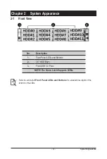
System Hardware Installation
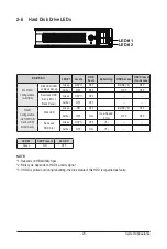
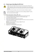
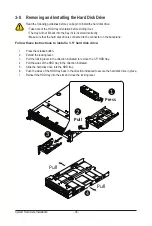
3-4 Removing and Installing the CPU
Read the following guidelines before you begin to install the CPU:
• Make sure that the motherboard supports the CPU.
• Always turn off the computer and unplug the power cord from the power outlet before installing
the CPU to prevent hardware damage.
• Unplug all cables from the power outlets.
• Disconnect all telecommunication cables from their ports.
• Place the system unit on a flat and stable surface.
• Open the system according to the instructions.
WARNING!
Failure to properly turn off the server before you start installing components may cause serious
damage. Do not attempt the procedures described in the following sections unless you are a
qualified service technician.
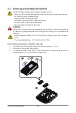
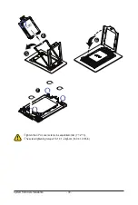
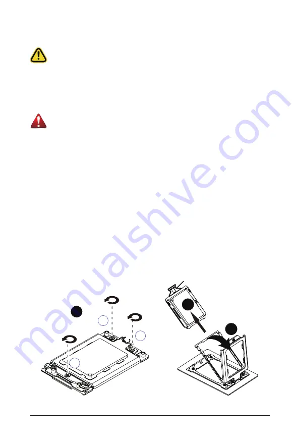
Follow these instructions to install the CPU:
1. Loosen the three captive screws securing the CPU cover in sequential order (1
g
2
g
3).
2. Flip open the CPU cover.
3. Remove the CPU carrier from the CPU frame using the handle on the CPU carrier.
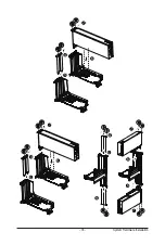
4. Using the handle on the CPU carrier insert the new CPU carrier with CPU installed into the CPU
frame.
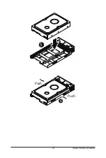
NOTE:
Ensure the CPU is installed in the CPU carrier in the correct orientation, with the triangle
on the CPU aligned to the top left corner of the CPU carrier.
5. Flip the CPU frame with CPU installed into place in the CPU socket.
6. Flip the CPU cover into place over the CPU socket.
7. Tighten the CPU cover screws in sequential order (1
g
2
g
3) to secure the CPU cover in place.
8. Repeat steps 1-7 for the second CPU.
9. To remove the CPUs, follow steps 1-7 in reverse order.
3
1
2
1
External cap
2
3
Содержание R282-Z96
Страница 1: ...R282 Z96 AMD EPYC 7002 DP Server System 2U 12 Bay GPU NVMe sku User Manual Rev 1 0 ...
Страница 10: ... 10 This page intentionally left blank ...
Страница 14: ...Hardware Installation 14 ...
Страница 16: ...Hardware Installation 16 1 3 System Block Diagram ...
Страница 24: ...System Appearance 24 This page intentionally left blank ...
Страница 35: ... 35 System Hardware Installation 4 5 6 7 4 5 6 7 5 6 6 7 7 9 4 ...
Страница 39: ... 39 System Hardware Installation 5 Push Push 6 ...
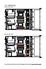
Страница 43: ... 43 System Hardware Installation Onboard SATA Cable Onboard SATA Cable 3 12 Cable Routing ...
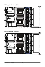
Страница 44: ...System Hardware Installation 44 HDD Backplane Board Power Cable HDD Backplane Board Signal Cable ...
Страница 45: ... 45 System Hardware Installation Front Panel USB 3 0 Ports Cable Front Panel LEDs and Buttons Cable ...
Страница 46: ...System Hardware Installation 46 GPU Card Power Cable ...
Страница 47: ... 47 System Hardware Installation NVMe Card Cable CNV3134 U2_A U2_8 CNV3134 U2_B U2_9 ...
Страница 48: ...System Hardware Installation 48 NVMe Card Cable CNV3134 U2_C U2_10 CNV3134 U2_D U2_11 ...
Страница 52: ...Motherboard Components 52 This page intentionally left blank ...
Страница 74: ...BIOS Setup 74 5 2 11 SATA Configuration ...
Страница 79: ... 79 BIOS Setup 5 2 16 Intel R I350 Gigabit Network Connection ...
Страница 81: ... 81 BIOS Setup 5 2 17 VLAN Configuration ...


