


- 19 -
System Appearance
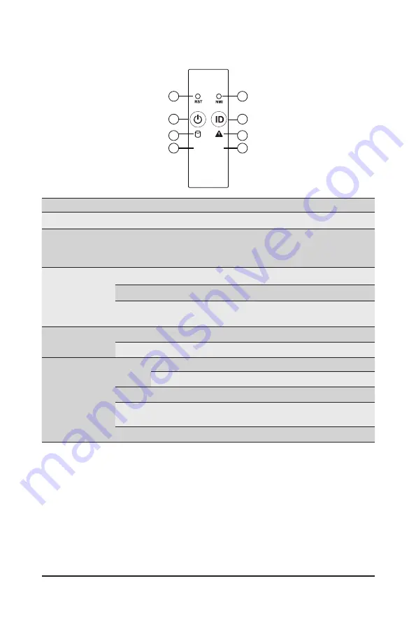
2-3 Front Panel LED and Buttons
No. Name
Color
Status
Description
1.
Reset Button
--
--
Press this button to reset the system.
2.
NMI button
--
--
Press this button for the server to generate a NMI to the
processor. If multiple-bit ECC errors occur, the server will
effectively be halted.
3.
Power button
with LED
Green
On
Indicates the system is powered on.
Green
Blink
System is in ACPI S1 state (sleep mode).
N/A
Off
• System is not powered on or in ACPI S5 state (power off)
• System is in ACPI S4 state (hibernate mode)
4.
ID Button
with LED
Blue
On
Indicates the system identification is active.
N/A
Off
Indicates the system identification is disabled.
5.
HDD Status
LED
Green
On
Indicates locating the HDD.
Blink
Indicates accessing the HDD.
Amber
On
Indicates HDD error.
Green/
Amber
Blink
Indicates HDD rebuilding.
N/A
Off
Indicates no HDD access or no HDD error.
L1
L2
1
2
4
6
8
7
5
3
Содержание R272-Z30
Страница 1: ...R272 Z30 R272 Z31 R272 Z32 AMD EPYC 7003 UP Server System 2U 24 Bay User Manual Rev 1 0 ...
Страница 15: ... 15 Hardware Installation 1 3 System Block Diagram ...
Страница 16: ...Hardware Installation 16 ...
Страница 24: ...System Appearance 24 This page intentionally left blank ...
Страница 42: ...System Hardware Installation 42 HBA Card to SAS Expander Card Cable ...
Страница 49: ... 49 Motherboard Components This page intentionally left blank ...
Страница 56: ...BIOS Setup 56 When Boot Mode Select is set to Legacy in the Boot Boot Mode Select section ...
Страница 61: ... 61 BIOS Setup 5 2 4 1 Serial Port 1 2 Configuration ...
Страница 69: ... 69 BIOS Setup 5 2 8 PCI Subsystem Settings ...
Страница 79: ... 79 BIOS Setup 5 2 16 Intel R I350 Gigabit Network Connection ...
Страница 81: ...BIOS Setup 81 5 2 17 VLAN Configuration ...
Страница 84: ... 84 BIOS Setup 5 2 19 MAC IPv6 Network Configuration ...
Страница 87: ...BIOS Setup 87 5 3 1 CPU Common Options ...