


Hardware Installation
- 25 -
English
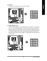
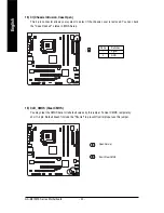
8) F_PANEL (Front Panel Jumper)
Please connect the power LED, PC speaker, reset switch and power switch etc of your chassis
front panel to the F_PANEL connector according to the pin assignment below.
1
2
19
20
HD-
HD+
RES+
RES-
NC
SPEAK-
MSG-
MSG+
PW-
PW+
SPEAK+
Speaker Connector
IDE Hard Disk
Active LED
Message LED/
Power/
Sleep LED
Power
Switch
Reset Switch
HD (IDE Hard Disk Active LED)
Pin 1: LED anode(+)
Pin 2: LED cathode(-)
SPEAK (Speaker Connector)
Pin 1: Power
Pin 2- Pin 3: NC
Pin 4: Data(-)
RES (Reset Switch)
Open: Normal
Close: Reset Hardware System
PW (Power Switch)
Open: Normal
Close: Power On/Off
MSG(Message LED/Power/Sleep LED)
Pin 1: LED anode(+)
Pin 2: LED cathode(-)
NC
NC
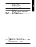
9) WOL (Wake On LAN)
1
Pin No.
Definition
1
+5V SB
2
GND
3
Signal
Содержание GA-8I915ME Series
Страница 2: ...Motherboard GA 8I915ME May 27 2005 May 27 2005 Motherboard GA 8I915ME ...
Страница 8: ... 8 ...
Страница 32: ...GA 8I915ME Series Motherboard 32 English ...
Страница 50: ...GA 8I915ME Series Motherboard 50 English ...
Страница 54: ...GA 8I915ME Series Motherboard 54 English ...
Страница 77: ...Appendix 77 English ...
Страница 78: ...GA 8I915ME Series Motherboard 78 English ...