System Hardware Installation
- 30 -
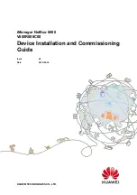
3-5-4 Processor and Memory Module Matrix Table
4 DIMM
Memory Q’ty
for each CPU
CPU1
J0
I0
L0
K0
O0
P0
M0
N0
V
1 DIMM
2 DIMM
6 DIMM
8 DIMM
V
V
V
V
V
V
V
V
V
V
V
V
V
V
V
V
V
V
V
V
CPU0
B0
A0
D0
C0
G0
H0
E0
F0
V
V
V
V
V
V
V
V
V
V
V
V
V
V
V
V
V
V
V
V
V
NOTE!
l
There should be at least one DDR4 DIMM per socket.
l
If only one DIMM is populated in a channel, then populate it in the slot furthest away from CPU of that channel.
l
Channel 0's on each memory controller (A/E/C/G, I/M/K/O) must be populated with same total capacity per channel
(if populated).
l
Channel 1's on each memory controller (B/F/D/H, J/N/L/P) must be populated with same total capacity per channel
(if populated).
Содержание G262-IR0
Страница 1: ...G262 IR0 HPC Server NVIDIA HGX A100 4 GPU 3rd Gen Intel Xeon Scalable GPU Server User Manual Rev 1 0 ...
Страница 13: ...Hardware Installation 15 1 3 System Block Diagram ...
Страница 25: ... 27 System Hardware Installation 4 1 2 3 4 5 6 ...
Страница 33: ... 35 System Hardware Installation 3 10 Cable Routing Front Switch Cable Front LED Cable GPU Power Cable ...
Страница 34: ...System Hardware Installation 36 HDD Back Plane Board Power Cable HDD Back Plane Board Signal Cable ...
Страница 35: ... 37 System Hardware Installation HDD Back Panel Board NVMe Signal Cable ...
Страница 36: ...System Hardware Installation 38 PCIe Signal Cable ...
Страница 37: ... 39 System Hardware Installation System Power Cable Power Supply Signal Cable ...
Страница 38: ...System Hardware Installation 40 On Board SATA Cable ...
Страница 62: ...BIOS Setup 64 5 3 1 Processor Configuration ...
Страница 75: ... 77 BIOS Setup 5 3 7 PCH Configuration Note 1 Only appears when HDD sets to RAID Mode ...