


System Hardware Installation
- 26 -
3-3 Removing and Installing the CPU
Read the following guidelines before you begin to install the CPU:
• Make sure that the motherboard supports the CPU.
• Always turn off the computer and unplug the power cord from the power outlet before installing the
CPU to prevent hardware damage.
• Unplug all cables from the power outlets.
• Disconnect all telecommunication cables from their ports.
• Place the system unit on a flat and stable surface.
• Open the system according to the instructions.
WARNING!
Failure to properly turn off the server before you start installing components may cause serious
damage. Do not attempt the procedures described in the following sections unless you are a
qualified service technician.
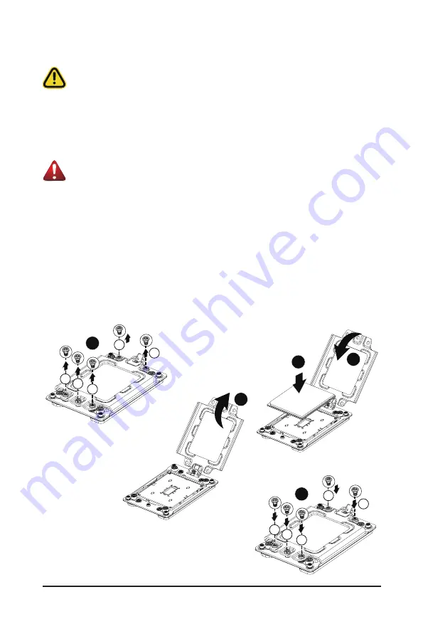
Follow these instructions to install the CPU:
1. Loosen the three captive screws securing the CPU cover in sequential order (1
g
2
g
3
g
4
g
5).
2. Flip open the CPU cover.
3. Remove the CPU carrier from the CPU frame using the handle on the CPU carrier.
4. Install the CPU into place in the CPU socket.
5. Flip the CPU cover into place over the CPU socket.
6. Tighten the CPU cover screws in sequential order (1
g
2
g
3
g
4
g
5) to secure the CPU cover in
place.
7. To remove the CPUs, follow steps 1-6 in reverse order.
1
1
3
4
5
2
2
3
4
5
5
3
2
1
4
Содержание G242-P33
Страница 14: ...Hardware Installation 14 1 3 System Block Diagram 1 3 1 G242 P33 ...
Страница 15: ... 15 Hardware Installation 1 3 2 G242 P34 ...
Страница 16: ...Hardware Installation 16 This page intentionally left blank ...
Страница 27: ... 27 System Hardware Installation 4 2 3 1 6 ...
Страница 38: ...System Hardware Installation 38 System Main Power Cable MB Bo om Power Connector MB Bo om Power Connector ...
Страница 39: ... 39 System Hardware Installation HDD Backplane Board Power Cable HDD Backplane Board Signal Cable ...
Страница 40: ...System Hardware Installation 40 PMBus Signal Cable MB Bo om Power Connector GPU Riser Card Power Cable ...
Страница 41: ... 41 System Hardware Installation ...
Страница 42: ...System Hardware Installation 42 GPU Signal Cable ...
Страница 43: ... 43 System Hardware Installation GPU Card Power Cable Reserved SATA Card Cable PS ON Signal Cable ...
Страница 45: ... 45 System Hardware Installation System Main Power Cable MB Bo om Power Connector ...
Страница 46: ...System Hardware Installation 46 HDD Backplane Board Power Cable HDD Backplane Board Signal Cable ...
Страница 47: ... 47 System Hardware Installation PMBus Signal Cable MB Bo om Power Connector GPU Riser Card Power Cable ...
Страница 48: ...System Hardware Installation 48 GPU Signal Cable MB Bo om Power Connector ...
Страница 49: ... 49 System Hardware Installation GPU Card Power Cable Reserved SATA Card Cable PS ON Signal Cable ...
Страница 50: ...System Hardware Installation 50 This page intentionally left blank ...
Страница 54: ...Motherboard Components 54 This page intentionally left blank ...
Страница 65: ... 65 BIOS Setup 5 2 6 PCI Subsystem Settings ...
Страница 69: ... 69 BIOS Setup 5 2 6 2 PCI Express GEN 2 Settings ...
Страница 79: ... 79 BIOS Setup 5 2 14 Intel R I350 Gigabit Network Connection ...