


- 18 -
System Appearance
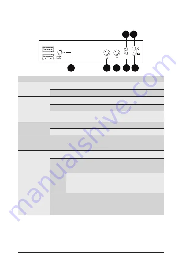
2-3 Front Panel LEDs and Buttons
NMI
RST
6
7
1
3
2
4 5
No. Name
Color
Status
Description
1.
ID Button with
LED
(Note)
Blue
On
Indicates the system identification is active.
N/A
Off
Indicates the system identification is disabled.
2.
Power button
with LED
Green
On
Indicates the system is powered on.
Green
Blink
System is in ACPI S1 state (sleep mode).
N/A
Off
- System is not powered on or in ACPI S5 state (power off)
- System is in ACPI S4 state (hibernate mode)
3.
ID Button
with LED
Blue
On
Indicates the system identification is active.
N/A
Off
Indicates the system identification is disabled.
4.
NMI button
--
--
Press this button for the server to generate a NMI to the
processor. If multiple-bit ECC errors occur, the server will
effectively be halted.
5.
System Status
LED
(Note)
Green
On
Indicates system is operating normally.
Amber
On
Indicates a critical condition, may include:
- System fan failure
- System temperature
Blink
Indicates non-critical condition, may include:
- Redundant power module failure
- Temperature and voltage issue
- Chassis intrusion
N/A
Off
Indicates system is not ready, may include:
- POST error
- NMI error
- Processor or terminator is missing
(Note) If your server features RoT function, please see the following section for detail LED behavior.
Содержание G152-Z12
Страница 1: ...G152 Z12 HPC Server 1U UP Gen4 GPU Server User Manual Rev 1 0 ...
Страница 10: ... 10 This page intentionally left blank ...
Страница 15: ... 15 Hardware Installation 1 3 System Block Diagram ...
Страница 38: ... 38 System Hardware Installation Motherboard Power Cable PMBus Cable ...
Страница 39: ...System Hardware Installation 39 Management LAN Signal Cable OCP 3 Signal Cable ...
Страница 40: ...System Hardware Installation 40 HDD Backplane Board Power Cable HDD Backplane Board Signal Cable ...
Страница 41: ...System Hardware Installation 41 GPU Riser Card Power Cable GPU Signal Cable ...
Страница 42: ...System Hardware Installation 42 NVMe 1 2 Cable Top Bottom NVMe 3 4 Cable Top Bottom ...
Страница 51: ...BIOS Setup 51 When Boot Mode Select is set to Legacy in the Boot Boot Mode Select section ...
Страница 56: ...BIOS Setup 56 5 2 4 1 Serial Port 1 Configuration ...
Страница 64: ...BIOS Setup 64 5 2 8 PCI Subsystem Settings ...
Страница 75: ...BIOS Setup 75 5 2 17 Intel R Ethernet Controller X550 ...
Страница 81: ...BIOS Setup 81 5 3 1 CPU Common Options ...
Страница 94: ...BIOS Setup 94 5 3 3 1 1 Enforce POR ...
Страница 140: ...BIOS Setup 140 This page intentionally left blank ...