16. Open interior airlock door and pull sliding tray into the work area.
17. Remove items from the tray and slide tray back into the airlock.
18. Close and latch the inside airlock door.
19. Begin preparation.
20. Dispose of any waste by removing the stopper and pushing waste down the tube. Replace
the stopper to maintain containment.
21. Dispose of any sharps by removing the stopper and dropping the syringe/needle down the
tube. Replace the stopper to maintain containment.
22. Remove completed preparation from the work area by placing in the airlock.
Always operate with critical sites in first air. This may take practice since the source of the
HEPA filtered air is now above the user instead of in front, as in the commonly used
Horizontal Laminar Flow Workstation.
The LFGI is not a substitute for good aseptic technique. It will provide a clean environment
for compounding but can be defeated with poor technique and disregard for cleaning and
operational procedures.
Airlock Operation
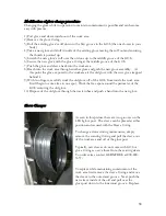
The Airlock provides a sealed transfer area between the work area and the ambient room
conditions. The sealed doors are fitted with adjustable compression hinges to ensure a tight
seal against cross contamination.
The Airlock is equipped with a HEPA purge function to clean the air trapped in the sealed
transfer area. A blower inside of the control panel pulls air out of the airlock. This air is
replaced with air pulled through the HEPA filter on the rear of the airlock. The air being
pulled from the airlock is also HEPA filtered. This filter is housed below the control panel.
The purge is timed and can be adjusted by your certifier to reflect cleaner ambient
conditions. The timer is set for worse case scenario at the factory. The purge of air is
initiated by pushing the large red button at the front of the control panel. During operation
of the purge, a red light adjacent to the red button will illuminate. This light will remain on
until all air is purged from the airlock and is replaced by clean HEPA filtered air.
This process ensures that the cleanliness level of the air inside of the airlock is equal to or
greater than that of the work area.
23
Содержание LFGI-3USP
Страница 1: ...Laminar Flow LFGI CAI or CACI User Manual ...
Страница 33: ...33 ...
Страница 51: ...SECTION IV UNIT DIAGRAM Made in the USA and available for purchase on the GSA 51 ...
Страница 55: ...55 ...
Страница 59: ...59 ...
Страница 63: ...Fig 2 Air recycle plenum connection tip removed 63 ...
Страница 85: ... 863 248 2800 www sensocon com 20 Installation and Operation Manual Series A3 A4 ...


