GeoVision GV-BL2511-E Скачать руководство пользователя страница 103


90 


6.3.2  Adjusting Lens  

To adjust the camera’s zoom and focus, follow the steps below. 
 
1. 

Loosen the camera’s cover. See

 Figure 6-2

.


2. 

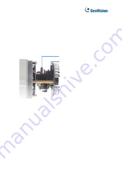
To adjust for image clarity by adjusting the focus and zoom screws. 
For details, see 

8.3 Adjusting Image Clarity


Zoom Screw

Focus Screw


Figure 6-11 

Содержание GV-BL2511-E

Страница 1: ...Firmware Manual GV IP Camera Before attempting to connect or operate this product please read these instructions carefully and save this manual for future use ICH265HISIV114 A ...

Страница 2: ...ty is assumed for incidental or consequential damages arising from the use of the information or products contained herein Features and specifications are subject to change without notice Note no memory card slot or local storage function for Argentina GeoVision Inc 9F No 246 Sec 1 Neihu Rd Neihu District Taipei Taiwan Tel 886 2 8797 8377 Fax 886 2 8797 8335 http www geovision com tw Trademarks us...

Страница 3: ...s the power supply for its internal real time clock RTC The battery should not be replaced unless required If the battery does need replacing please observe the following Danger of Explosion if battery is incorrectly replaced Replace only with the same or equivalent battery as recommended by the manufacturer Dispose of used batteries according to the manufacturer s instructions ...

Страница 4: ...x Note for Waterproofing Failures xi Chapter 1 Bullet Camera Part I 1 1 1 Packing List 3 1 2 Overview 4 1 3 Installation 5 1 3 1 Connecting the Camera 7 1 3 2 Adjusting the Angles 11 1 3 3 Adjusting Lens and Inserting a Memory Card 15 1 3 4 Installing the Sun Shield Cover 18 1 4 Loading Factory Default 19 1 4 1 Using the Web Interface 19 1 4 2 Directly on the Camera 20 Chapter 2 Bullet Camera Part...

Страница 5: ...Default 53 3 5 1 Using the Web Interface 53 3 5 2 Directly on the Camera 53 Chapter 4 Ultra Bullet Camera 54 4 1 Packing List 56 4 2 Overview 57 4 3 Installation 59 4 3 1 Waterproofing the Cable 64 4 3 2 Connecting the Camera 66 4 4 Loading Factory Default 69 4 4 1 Using the Web Interface 69 4 4 2 Directly on the Camera 69 Chapter 5 Target Bullet Camera Part I 70 5 1 Packing List 71 5 2 Overview 7...

Страница 6: ...oading Factory Default 93 6 5 1 Using the Web Interface 93 6 5 2 Directly on the Camera 93 Chapter 7 Target Bullet Camera Part III 94 7 1 Packing List 95 7 2 Overview 96 7 3 Installation 97 7 4 Connecting the Camera 98 7 4 1 Wire Definition 98 7 4 2 Power Connection 98 7 5 Loading Factory Default 99 7 5 1 Using the Web Interface 99 7 5 2 Directly on the Camera 99 Chapter 8 Accessing the Camera 100...

Страница 7: ...v 8 3 Adjusting Image Clarity 106 Chapter 9 The Web Interface 108 Chapter 10 Upgrading System Firmware 111 ...

Страница 8: ... PoE adapter is designed to provide power and network connection to the cameras over a single Ethernet cable GV POE The GV POE is designed to provide power along with network connection for IP devices The GV POE is available in various models with different numbers and types of ports Power Adapter The power adapter is available for all Bullet Camera Ultra Bullet Camera except GV BL2511 E 5311 E an...

Страница 9: ...ra 1 Download and install GV IP Device Utility from the company website 2 On the GV IP Device Utility window click to search for your GV IP camera 3 Double click your GV IP camera in the GV IP Device Utility list This dialog box appears 4 Click the Change Username and Password tab to type a new username and password Note that the new password must meet the password strength requirements 5 Optional...

Страница 10: ...over tighten the Focus and Zoom screws The screws only need to be as tight as your finger can do it It is not necessary to use any tools to get them tighter Doing so can damage the structure of lens For example Zoom Screw Focus Screw The maximum torque value for all the zoom and focus screws is 0 049 N m ...

Страница 11: ...nstalling the cameras outdoor be sure that 1 The camera is set up above the junction box to prevent water from entering the camera along the cables 2 Any PoE power audio and I O cables are waterproofed using waterproof silicon rubber or the like ...

Страница 12: ...a gel bag loses its effectiveness when the dry camera is opened To prevent the lens from fogging up replace the silica gel bag every time you open the camera and conceal the gel bag in camera within 2 minutes of exposing to open air 2 When the camera is shipped a silica gel bag will be included inside the camera For the first time user replace the silica gel bag prior to the installation to avoid ...

Страница 13: ...ofing Failures To avoid waterproofing failures do not open the screw on the camera body The screw on Ultra Bullet Camera The screw on Target Bullet Camera The screw on GV EBL2101 2111 3101 5101 The screw on GV BL3700 5700 ...

Страница 14: ...in night vision applications The models described in this chapter use auto iris which allows for automatic control of exposure The WDR Pro models enhance the image by processing contrasting intensity of light The super low lux models can produce color live view in near darkness The motorized varifocal lens models allow the user to adjust the focus and zoom through the Web interface ...

Страница 15: ... H 264 Super Low Lux GV BL3400 Varifocal lens Auto Iris f 3 9 mm F 1 2 1 2 7 ø 14 mm Lens Mount 3 MP H 264 WDR Pro GV BL1210 1 3 MP H 264 Low Lux 3X Optical Zoom GV BL2410 2 MP H 264 WDR Pro 3X Optical Zoom GV BL3410 Auto Iris f 3 9 mm F 1 2 1 2 7 ø 14 mm Lens Mount 3 MP H 264 WDR Pro 3X Optical Zoom GV BL5310 Motorized varifocal lens Auto Iris f 4 5 9 mm F 1 2 1 2 7 ø 14 mm Lens Mount 5 MP H 264 ...

Страница 16: ...lastic Screw Anchor x 3 Torx Wrench x 2 Sun Shield Cover Kit Sun Shield Cover Philips Head Screw x 2 Plastic Screw Spacer x 2 and Hexagon Screw x 2 Silica Gel Bag x 2 2 Pin Terminal Block Power Adapter Download Guide Warranty Card Note The power adapter can be excluded upon request ...

Страница 17: ...y Card Slot Receives a micro SD card SD SDHC version 2 0 only Class 10 2 Zoom Screw Holds the zoom lens in place 3 Focus Screw Holds the focus lens in place 4 Default Button Resets all configurations to factory default For details see 1 4 Loading Factory Default ...

Страница 18: ...n of the Bullet Camera 1 Slide the cable clamp to the camera base Cable Clamp Figure 1 2 2 Install the Bullet Camera to the wall Figure 1 3 3 Remove the protection sticker from the camera s cover 4 Connect the power network and other wires to the Bullet Camera See 1 3 1 Connecting the Camera ...

Страница 19: ...1 3 2 Adjusting the Angles 7 Loosen the camera s cover adjust the focus of the camera and optionally insert a micro SD card SD SDHC version 2 0 Class 10 into the SD card slot See 1 3 3 Adjusting Lens and Inserting a Memory Card 8 Fasten the camera s cover 9 Install the sun shield cover to the Bullet Camera For details see 1 3 4 Installing the Sun Shield Cover ...

Страница 20: ...he wires are illustrated and defined below Ethernet PoE Digital In Red DC 12V AC 24V Brown Digital Out Orange DC 12V AC 24V Black GND Yellow Audio In Red Audio Out Green Figure 1 4 No Wire Color Definition 1 Red Digital In 2 Brown DC 12V AC 24V 3 Orange Digital Out 4 Black DC 12V AC 24V 5 Yellow Ground 6 Red RCA Audio in 7 Green RCA Audio out Note Audio In and Out connectors may also come as termi...

Страница 21: ...camera to the network and the power will be provided at the same time Plug the power adaptor to the terminal block as shown below Insert the black wire of the Bullet Camera to the left pin and the brown wire to the right pin Figure 1 5 Connect the DC 12V Power Adapter to the Terminal Block DC 12V Power Adaptor Terminal Block Figure 1 6 ...

Страница 22: ...r details on how to enable an installed I O device see 4 2 I O Settings GV IPCam Firmware Manual Voltage Load Expansion Optional The camera can only drive a maximum load of 200mA 5V DC To expand the maximum voltage load to 10A 250V AC 10A 125V AC or 5A 100V DC connect the camera to a GV Relay V2 module optional product Refer to the figure and table below Output Devices Connect to Power Figure 1 8 ...

Страница 23: ...10 GV Relay V2 Bullet Camera COM Ground Yellow DO1 Digital Out Orange ...

Страница 24: ... easy and flexible installation First Shaft You can adjust the camera body by 360 degrees to the right or the left 1 Unscrew the panning lock screw with the torx wrench Torx Wrench Panning Lock Screw Figure 1 9 2 Adjust the angle of camera body to the right or the left and fasten the panning lock screw 0 360 Figure 1 10 ...

Страница 25: ...e gears inside the camera body and the camera base 1 Unscrew the tilting lock screw with the torx wrench Torx Wrench Tilting Lock Screw Figure 1 11 2 Hold the camera body and move the camera base to the right to separate the camera gears Camera Body Camera Gears Move the Camera Base to the Right Figure 1 12 ...

Страница 26: ... 5 or 180 Then move the camera base to the left to combine the gears 90 112 5 180 157 5 135 Figure 1 13 4 Fasten the tilting lock screw Third Shaft You can adjust the camera base by 360 1 Unscrew the base fixing screw with the torx wrench Torx Wrench Base Fixing Screw Figure 1 14 ...

Страница 27: ...14 2 Adjust the angle of camera base and fasten the base fixing screw 0 360 Figure 1 15 ...

Страница 28: ...d To adjust the camera s zoom and focus or to insert a micro SD card SD SDHC version 2 0 only Class 10 follow the steps below 1 Loosen the camera s cover Camera s Cover Figure 1 16 For GV BL2511 E 5311 E loosen the camera s cover and the screw as indicated below Figure 1 17 ...

Страница 29: ...3 Adjusting Image Clarity Silica Gel Bag Zoom Screw Focus Screw Figure 1 18 For motorized varifocal lens models adjust for image clarity through the Web interface For details see Zoom Focus Change and Focus Mode settings in 3 2 2 The Control Panel of the Live View Window GV IPCam Firmware Manual 3 To insert a micro SD card follow the steps below 4 Loosen the fixing screw Fixing Screw Figure 1 19 5...

Страница 30: ...ard into the memory card slot Memory Card Slot Figure 1 20 7 Push the camera back and fasten the fixing screw 8 Insert a new silica gel bag to the camera module and fasten the camera s cover Silica Gel Bag Figure 1 21 Figure 1 22 GV BL2511 E 5311 E ...

Страница 31: ... top or below the camera Hexagon Screws Figure 1 23 2 Put the sun shield cover on top of hexagon screws Make sure to aim the rear hexagon screw at the edge of the sun shield cover s aperture for optimal sun shield performance Sun Shield Cover Figure 1 24 3 Fasten the Philips head screws with the plastic screw spacers Philips Head Screw Plastic Screw Spacer Figure 1 25 ...

Страница 32: ...fault settings through the Web interface or directly on the camera 1 4 1 Using the Web Interface 1 On the left menu of Web interface select Management and select Tools The Additional Tools dialog box appears 2 Click the Load Default button in the System Settings section Figure 1 26 ...

Страница 33: ... Loosen the camera s cover 3 Press and hold the default button for 8 seconds Default Button Figure 1 27 4 Release the default button When the process of loading default settings is completed the camera reboots automatically 5 Replace the Silica Gel Bag and fasten the camera s cover immediately ...

Страница 34: ...this chapter use P Iris which allows for precise control of exposure producing images with better clarity and contrast The WDR Pro models enhance the image by processing contrasting intensity of light The super low lux models can produce color live view in near darkness The motorized varifocal lens models allow the user to adjust the focus and zoom through the Web interface The arctic models can w...

Страница 35: ...ris f 6 50 mm F 1 6 1 2 7 ø 14 mm Lens Mount GV BL2702 5V P Iris f 9 22 mm F 2 0 1 2 7 ø 14 mm Lens Mount 2 MP H 265 Super Low Lux WDR Pro GV BL4702 Varifocal lens P Iris f 2 8 12 mm F 1 7 1 2 7 ø 14 mm Lens Mount 4 MP H 265 Super Low Lux WDR Pro GV BL1511 1 3 MP H 264 Super Low Lux 3X Optical Zoom GV BL2511 2 MP H 264 Super Low Lux 3X Optical Zoom GV BL3411 Motorized varifocal lens P Iris f 3 9 m...

Страница 36: ... mm Lens Mount 4 MP H 265 Super Low Lux WDR Pro GV BL5713 Motorized varifocal lens P Iris f 4 8 mm F 1 63 1 1 8 ø 14 mm Lens Mount 5 MP H 265 Low Lux WDR GV BL2511 E P Iris f 3 9 mm F 1 2 1 2 7 ø 14 mm Lens Mount 2 MP H 264 Super Low Lux 3X Optical Zoom GV BL5311 E Motorized varifocal lens Extreme temperature tolerance P Iris f 4 5 9 mm F 1 2 1 2 7 ø 14 mm Lens Mount 5 MP H 264 2X Optical Zoom ...

Страница 37: ... Screw x 2 Silica Gel Bag x 2 2 Pin Terminal Block 3 Pin Terminal Block Power Adapter Installation Sticker Ruler Stand Kit Conduit Converter PG21 Conduit Connector RJ 45 Connector M3 Screw x 2 Cable Tie Mounting Kit M4 Screw x 3 Nut x 3 Plate x 3 Download Guide Warranty Card Note 1 The power adapter can be excluded upon request 2 The Mounting Kit is used for wall corner and pole installations usin...

Страница 38: ...ounting Kit M4 Screw x 3 Nut x 3 Plate x 3 Screw Anchor x 3 Screw for Mounting Kit x 3 Hex Wrench 4 mm Wrench 2 5 mm Wrench Silica Gel Bag x 2 Ruler Installation Sticker Download Guide Warranty Card Note 1 GV BL4713 5713 does not include the Sun Shield Cover Kit in the packing list since the sun shield cover is installed to the camera upon delivery 2 The Mounting Kit is used for wall corner and po...

Страница 39: ...the camera cover to access the following 1 2 3 4 Figure 2 1 GV BL4713 5713 For GV BL4713 5713 twist off the camera cover and loosen the three screws on the front lid of the sun shield cover to access the following 1 4 Figure 2 2 ...

Страница 40: ...lens in place 4 Default Button Resets all configurations to factory default For details see 1 4 Loading Factory Default Note 1 The memory card slot of GV BL2702 4702 4713 5713 supports micro SD card SD SDHC SDXC UHS I Class 10 2 To insert an SD card into GV BL4713 5713 loosen the screw indicated in the following left picture and then open the sun shield cover to access the SD card slot Figure 2 3 ...

Страница 41: ...gure 2 4 No Name Description 1 LAN PoE Connects to a 10 100 Ethernet or PoE 2 Audio In Connects a microphone for audio input 3 Audio Out Connects a speaker for audio output 4 I O Terminal Block Connects to I O devices For details see I O Terminal 2 4 Connecting the Camera 5 DC 12V Port Connects to power ...

Страница 42: ...supplied sticker to the ceiling wall For wall installations make sure the arrow on the sticker points toward the ceiling Mount template Figure 2 5 2 Drill the shaded area and insert the screw anchor into the three holes 3 Loosen the indicated screws with the supplied torx wrench to remove the base Figure 2 6 ...

Страница 43: ...30 4 Loosen the indicated screws and remove the back plate Figure 2 7 5 Align and secure the back plate to the wall ceiling with the supplied self tapping screws Figure 2 8 ...

Страница 44: ... on the type of the back plate that comes with your camera A If your plate comes with two knobs as in Figure 2 9 Install the supplied conduit converter to the back plate Figure 2 9 B If your plate comes without knobs install the conduit converter to the camera Conduit Converter PG21 Conduit Connector Figure 2 10 ...

Страница 45: ...ctor Figure 2 11 B Thread an Ethernet cable with no RJ 45 connector on one end from the back panel through the cable seal and then through the conduit converter optionally installed at Step 6A Figure 2 12 IMPORTANT Use the supplied ruler and leave about 10 cm of the Ethernet cable between the connector and the cable seal ...

Страница 46: ...ved conduit connector You should have 4 parts 1 2 3 4 Figure 2 13 B Remove the terminal block from the supplied power adapter C Optionally thread audio wires adapter wires and I O wires through the conduit converter and then through part 1 2 3 and 4 of the conduit connector Tip To make the threading easier it is advised to thread the wires in the order described here ...

Страница 47: ...igure 2 15 IMPORTANT Use the supplied ruler and leave about 10 cm of audio power and I O wires between their connectors and the cable seal The plugs are used to prevent water from entering the camera housing Keep the unused holes plugged and save the removed plugs for future use Only thread the wires through their designated holes on the conduit connector to make sure the wires are properly sealed...

Страница 48: ...he camera panel 11 Tie the wires with the supplied cable tie and re install the base to the camera You may need to rotate the base for the wires to fit Cable Tie Figure 2 16 12 Access the live view For details see 8 2 Accessing the Live View 13 Adjust the angles of the camera based on the live view Three shafts can be adjusted See 1 3 2 Adjusting the Angles 14 To adjust the focus and insert a micr...

Страница 49: ...t PoE adapter to connect the camera to the network and the power will be provided at the same time Plug the power adaptor to the terminal block as shown below For all models except GV BL2511 E 5311 E insert the striped wire to the left pin for GV BL2511 E 5311 E insert the striped wire to the right pin Figure 2 18 All Models except GV BL2511 E 5311 E Figure 2 19 GV BL2511 E 5311 E ...

Страница 50: ...y contact Pin Function 1 Digital Output 2 GND I O 1 2 3 Figure 2 18 3 Digital Input For details on how to enable an installed I O device see 4 2 I O Settings GV IPCam Firmware Manual I O Cable Optional For GV BL2702 4702 4713 5713 you can optionally purchase an I O cable for convenient connection 1 2 3 4 Figure 2 17 ...

Страница 51: ...ink RCA Audio Input 3 Green RCA Audio Output Red Digital Output Black GND 4 Digital I O Yellow Digital Input Note To connect a power adapter to the I O cable take off the 2 pin terminal block on the adapter and connect the wires to the one on the I O cable ...

Страница 52: ...chieve better video compression while maintaining high quality picture The cameras use P Iris which allows for precise control of exposure producing images with better clarity and contrast Model No Specifications Description GV BL3700 P Iris f 2 8 12 mm F 1 7 1 2 7 ø 14 mm Lens Mount 3 MP H 265 Super Low Lux WDR pro GV BL5700 Varifocal Lens P Iris f 4 8 mm F 1 65 1 1 8 ø 14 mm Lens Mount 5 MP H 26...

Страница 53: ...crew Anchor x 3 Silica Gel Bag x 2 Washer x 2 RJ 45 Connector x 2 Hex Wrench Screw for Mounting Kit x 3 Nut for Mounting Kit x 3 Download Guide Warranty Card Note The Mounting Kit is used for wall corner and pole installations using GV Mount300 310 400 410 optional For details see GV Mount Accessories Installation Guide ...

Страница 54: ... Card Slot Receives a micro SD card SD SDHC SDXC UHS I Class 10 UHS II card type is not supported 2 Default Button Resets all configurations to factory default For details see 3 5 Loading Factory Default 3 Focus Screw Holds the focus lens in place 4 Zoom Screw Holds the zoom lens in place ...

Страница 55: ...crew the camera body remove the sun shield mount and loosen the camera cover from the camera Screws Sun Shield Mount Camera Cover Figure 3 2 2 Insert a micro SD card SD SDHC SDXC UHS I Class 10 into the card slot 3 Tape two silica gel bags to the camera module Silica Gel Bag Micro SD Card Figure 3 3 ...

Страница 56: ...cover fasten the sun shield mount and screw the camera body Figure 3 4 5 Slide the sun shield cover onto the top of the camera Adjust the position of the cover before fully securing the cover with the washer and the screw Figure 3 5 Sun Shield Mount ...

Страница 57: ...ctor Figure 3 6 B Disintegrate the removed conduit connector Thread the Ethernet cable through the 3 parts Figure 3 7 C Assemble the conduit connector Figure 3 8 Note If you can t plug the self prepared RJ 45 connector into the jack of the conduit it is suggested to use the supplied RJ 45 connector ...

Страница 58: ...ack Figure 3 9 IMPORTANT To avoid waterproofing failures the top of the camera must be facing upward for wall mount 8 Connect the wires and cable connector to the camera See 3 4 Connecting the Camera 9 Access the live view For details see 8 2 Accessing the Live View 10 Adjust angles of the camera body based on the live view ...

Страница 59: ...justable in two shafts for easy and flexible installation First Shaft You can adjust the camera base by 360 1 Unscrew the base fixing screw with the hex wrench Figure 3 10 2 Adjust the angle of camera base and fasten the base fixing screw with the hex wrench Figure 3 11 ...

Страница 60: ...ou can adjust the camera body to the desired angle by tilting the camera module 1 Unscrew the tilting lock screw with the hex wrench Figure 3 12 2 Adjust the angle of camera body to the desired angle Figure 3 13 3 Fasten the tilting lock screw ...

Страница 61: ...he camera s zoom and focus follow the steps below Loosen the camera s cover See Figure 3 2 To adjust for image clarity by adjusting the focus and zoom screws For details see 8 3 Adjusting Image Clarity Zoom Screw Focus Screw Figure 3 14 ...

Страница 62: ...igital output of dry contact For details on how to enable an installed I O device see 4 2 I O Settings GV IPCam Firmware Manual The 5 Pin terminal block provides power input 1 audio input and 1 audio output The wires are illustrated and defined below Ethernet PoE 4 Pin terminal block 5 Pin terminal block 1 2 3 4 5 6 7 8 9 Figure 3 16 ...

Страница 63: ...DC 12V 7 L IN Audio in Support passive microphones only 8 A GND Audio Ground 9 5 pin terminal block L OUT Audio out Wire Definition RJ 45 Ethernet PoE IEEE 802 3af Note To connect an audio input output device cut its 3 5 mm audio jack and connect the wires to L IN and A GND for a microphone or L OUT and A GND for a speaker Figure 3 17 ...

Страница 64: ...ng methods to supply power to the camera Use a Power over Ethernet PoE adapter to connect the camera to the network and the power will be provided at the same time Connect the wires of your power adapter to the DC 12V and DC 12V pins of the 5 pin terminal blocks Figure 3 18 ...

Страница 65: ...aximum voltage load to 10A 250V AC 10A 125V AC or 5A 100V DC connect the camera to a GV Relay V2 module optional product Refer to the figure and table below Output Devices Connect to Power 1 2 3 4 5 6 7 8 9 Figure 3 19 GV Relay V2 Bullet Camera COM Digital In Digital Out DO1 4 Pin terminal block Digital Out ...

Страница 66: ...s through the Web interface For details refer to 1 4 1 Using the Web Interface 3 5 2 Directly on the Camera Press and hold the default button for about 5 seconds to restore the factory default After the ready LED blinks release the default button For details see 1 4 2 Directly on the Camera Default Button LED status Figure 3 20 ...

Страница 67: ...er to remotely adjust the focus and zoom through the Web interface The WDR Pro models can enhance the live view by processing contrasting intensity of lights The super low lux models are able to provide color live view in near darkness Model No Specifications Description GV UBL1211 1 3 MP Low Lux H 264 3X Optical Zoom GV UBL1511 1 3 MP Super Low Lux H 264 3X Optical Zoom GV UBL2411 2 MP H 264 WDR ...

Страница 68: ... Lens Mount 1 3 MP Low Lux H 264 GV UBL2401 0F Fixed Iris f 2 8 mm F 2 0 1 3 M12 Lens Mount GV UBL2401 1F Fixed Iris f 4 mm F 1 5 1 3 M12 Lens Mount GV UBL2401 2F GV UBL2401 3F Fixed Iris f 8 12 mm F 1 6 1 3 M12 Lens Mount 2 MP H 264 WDR Pro GV UBL3401 0F Fixed Iris f 2 8 mm F 2 0 1 3 M12 Lens Mount GV UBL3401 1F Fixed Iris f 4 mm F 1 5 1 3 M12 Lens Mount GV UBL3401 2F GV UBL3401 3F Fixed Lens Fix...

Страница 69: ...lastic Screw Anchor x 3 Torx Wrench Sun Shield Cover Kit Sun Shield Cover Philips Head Screw x 2 Plastic Screw Spacer x 2 and Hexagon Screw x 2 Cable connector for waterproof LAN connector only Silica Gel Bag x 2 2 Pin Terminal Block Data cable Power Adapter Download Guide Warranty Card Note The power adapter can be excluded upon request ...

Страница 70: ... details see 4 3 2 Connecting the Camera 2 Default Button Resets all configurations to factory default For details see 4 4 Loading Factory Default 3 LAN PoE Cable Connects to a 10 100 Ethernet or PoE 4 Memory Card Slot Receives a micro SD card SD SDHC version 2 0 only Class 10 5 Silica gel bag Desiccant that keeps the camera housing dry ...

Страница 71: ...era provides two connector types Select an option based on your installation environment Option 1 Waterproof To waterproof the cable install the supplied cable connector See 4 3 1 Waterproofing the Cable Option 2 Smaller and non waterproof ...

Страница 72: ...o SD card to the camera A Unscrew and open the back panel with the supplied torx wrench Figure 4 2 B Insert a micro SD card into the card slot and replace the silica gel bag see Figure 4 1 IMPORTANT Make sure the I O connector is firmly plugged C Secure the back cover with the supplied torx wrench 2 Install the sun shield cover to the camera ...

Страница 73: ... sun shield cover on the top of the camera For optimal sun shield performance make sure the rear hexagon screw is at the end of the opening Figure 4 4 IMPORTANT The GeoVision logo on the sun shield cover should be closer to the front of the camera Hexagon Screws Sun Shield Cover ...

Страница 74: ...the camera Ceiling Mount Fasten one Philips head screw to the top of the camera Wall Mount Fasten two Philips head screws to the top of the camera Philips Head Screw Plastic Screw Spacer Figure 4 5 3 Install the camera stand A Ceiling Mount Secure the black rubber and the camera stand to the screw hole on the top Figure 4 6 ...

Страница 75: ...2 B Wall Mount Secure the black rubber and the camera stand to one of the screw holes on the bottom Figure 4 7 4 Use the screw anchors and self tapping screws to secure the camera to the wall Figure 4 8 ...

Страница 76: ... 1 Waterproofing the Cable and 4 3 2 Connecting the Camera 7 Access the live view For details see 8 2 Accessing the Live View 8 Adjust angles of the camera body based on the live view 9 For varifocal models GV UBL1211 1511 2411 2511 3411 adjust the focus For details see 3 2 2 The Control Panel of the Live View Window GV IPCam Firmware Manual ...

Страница 77: ...tor can be dissembled into 5 parts 1 2 3 4 5 Figure 4 9 1 Cut off the RJ 45 connector on one end of the Ethernet cable Figure 4 10 2 Connect the Ethernet cable to the LAN PoE connector No 3 Figure 4 1 on the camera 3 Slide the components through the Ethernet cable as shown below 1 2 3 4 5 A Figure 4 11 4 Paste the item 1 sticker to item 2 ...

Страница 78: ...item 2 secure item 3 to the LAN PoE connector Item A and finally secure item 5 to item 2 tightly Figure 4 12 IMPORTANT Item 5 must be secured tightly to waterproof the LAN PoE connector 6 Prepare an RJ 45 connector reconnect the RJ 45 connector to the cable and then connect the camera to network ...

Страница 79: ...finition The camera s 4 pin data cable provides connections for power ground 1 sensor input and 1 alarm output The wires are defined below Figure 4 13 No Wire Color Definition 1 Red DC 5V 2 Green Digital In 3 Blue Digital Out 4 Black Ground ...

Страница 80: ...connect the camera to the network and the power will be provided at the same time Plug the power adaptor to the terminal block as shown below 1 Insert the black wire of the data cable to the left pin and the red wire to the right pin Figure 4 14 2 Connect the DC 5V power adapter to the terminal block DC 5V Power Adaptor Terminal Block Figure 4 15 ...

Страница 81: ... DC To expand the maximum voltage load to 10A 250V AC 10A 125V AC or 5A 100V DC connect the camera to a GV Relay V2 module optional product Refer to the figure and table below Output Devices Connect to power Figure 4 16 GV Relay V2 Ultra Bullet Camera DO1 Digital Out Blue COM Ground Black ...

Страница 82: ...restore factory default settings through the Web interface For details refer to 1 4 1 Using the Web Interface 4 4 2 Directly on the Camera Press and hold the default button for about 8 seconds to store the factory default For details see 1 4 2 Directly on the Camera Figure 4 17 Default button ...

Страница 83: ...ull protection against dust and jets of water The camera offers an entry level surveillance solution with all the essential features and excellent image quality Model No Specifications Description GV EBL1100 1F GV EBL2100 1F Fixed Iris f 6 mm F 1 8 1 2 7 ø 14 mm Lens Mount GV EBL1100 2F GV EBL2100 2F Fixed Lens Fixed Iris f 3 8 mm F 1 8 1 2 7 ø 14 mm Lens Mount 1 3 MP 2 MP H 264 Low Lux ...

Страница 84: ...t Target Bullet Camera Sun Shield Cover Silica Gel Tape x 2 Supporting Rack Screw for supporting rack x 3 Screw Anchor x 3 Screw for sun shield cover Washer Terminal Block Download Guide Warranty Card Note Power adapter can be purchased upon request ...

Страница 85: ... 1 Figure 5 1 No Name Description 1 Power Connector Connects to the data cable For details see 5 4 Connecting the Camera 2 Default Button Resets the camera to factory default For details see 5 5 Loading Factory Default ...

Страница 86: ...eiling or wall Follow the steps below 1 Slide the sun shield cover onto the top of the camera Figure 5 3 Note The GeoVision logo on the sun shield cover should be closer to the front of the camera 2 Line up the screw hole on the camera with the opening on the sun shield cover Figure 5 4 ...

Страница 87: ... Secure the supporting rack to the opening on the sun shield cover Figure 5 5 4 Wall Mount A Insert and tighten the supplied screw and washer on the sun shield cover B Secure the supporting rack to the bottom Figure 5 6 ...

Страница 88: ...75 5 5 Thread the Ethernet cable into the conduit connector For details see step 6 3 3 Installation Figure 5 7 Note The size of RJ 45 connector must be within 14 mm to plug into the jack of the conduit Unfit size of RJ45 Connector ...

Страница 89: ...tand the camera on a plain surface Figure 5 8 7 Remove the protection sticker from the camera s cover 8 Connect the wires and cable connector to the camera See 5 4 Connecting the Camera 9 Access the live view For details see 8 2 Accessing the Live View 10 Adjust angles of the camera body based on the live view ...

Страница 90: ...4 Connecting the Camera 5 4 1 Wire Definition The data cable provides connections for power ground and network access The wires are defined below Figure 5 9 No Wire Color Definition 1 Red DC 12V 2 Black Ground 3 Black thick PoE Ethernet ...

Страница 91: ...g the power adapter to the 12V terminal block as shown below The power adapter is an optional device 1 Insert the black wire of the data cable to the left pin and the red wire to the right pin Figure 5 10 2 Connect the DC 12V power adapter to the terminal block DC 12V Power Adaptor Terminal Block Figure 5 11 Note The Power Adaptor is not supplied in the packing list You need to self prepare this i...

Страница 92: ...The Additional Tools dialog box appears 4 Click the Load Default button of Restore to factory default settings or Restore to factory default settings Except network in the System Settings section Figure 5 12 Note The Restore to factory default settings Except network option is to restore the factory default settings without changing the camera s network settings ...

Страница 93: ...80 5 5 2 Directly on the Camera Press and hold the default button for about 8 seconds to restore the factory default For details see 1 4 2 Directly on the Camera Default button Figure 5 13 ...

Страница 94: ...ty and contrast It offers an entry level surveillance solution with all the essential features and excellent image quality Model No Specifications Description GV EBL2101 Varifocal Lens P Iris f 3 9 mm F 1 7 1 2 7 ø 14 mm Lens Mount 2 MP H 264 Super Low Lux GV EBL2111 Motorized Varifocal Lens P Iris f 2 8 12 mm F 1 7 1 2 7 ø 14 mm Lens Mount 2 MP H 264 Super Low Lux GV EBL3101 Varifocal Lens P Iris...

Страница 95: ...lica Gel Bag x 2 Screw for Supporting Rack x 3 Screw Anchor x 3 Screw for Sun shield Cover x 2 Washer x 2 Terminal Block Screw for Mounting Kit x 3 Nut for Mounting Kit x 3 Hex Wrench Download Guide Warranty Card Note Power adapter can be purchased upon request ...

Страница 96: ... 2 Overview 3 Figure 6 1 No Name Description 1 Zoom Screw Holds the zoom lens in place 2 Focus Screw Holds the focus lens in place 3 Default Button Resets all configurations to factory default For details see 6 5 Loading Factory Default ...

Страница 97: ...install the camera to the ceiling or wall Follow the steps below 1 Replace the Silica Gel Bag A Remove the camera cover from the camera Figure 6 2 B Loosen the camera s screws and the hexagon pillars as indicated below Figure 6 3 ...

Страница 98: ...the camera body Figure 6 4 D Cut the 2 silica gel bags apart with scissors and place the new silica gel bags at the lower half of the camera body Figure 6 5 2 Secure the 2 hexagon pillars to the upper and lower holes of camera module as indicated below Figure 6 6 ...

Страница 99: ...of the camera Adjust the position of the cover before fully securing the cover with the washer and the screw Figure 6 7 Note 1 The GeoVision logo on the sun shield cover should be closer to the front of the camera 2 There are two holes for the screws at the back of the camera You only need to fasten one screw to secure the sun shield cover ...

Страница 100: ...llet Camera Part II 87 6 5 Thread the Ethernet cable into the camera For details see step 6 3 3 Installation Figure 6 8 Note The size of RJ 45 connector must be within 14 mm to plug into the jack of the conduit ...

Страница 101: ... 9 7 Connect the wires and cable connector to the camera See 6 4 Connecting the Camera 8 Access the live view For details see 8 2 Accessing the Live View 9 Adjust angles of the camera body based on the live view IMPORTANT To avoid waterproofing failures the top of the camera must be facing upward for wall mount ...

Страница 102: ... Target Bullet Camera is designed to be adjustable in two shafts for easy and flexible installation You can adjust the camera base by 360 and the camera body to the desired angle by tilting the camera module For details see 3 3 1 Adjusting the Angles 360 Figure 6 10 ...

Страница 103: ... camera s zoom and focus follow the steps below 1 Loosen the camera s cover See Figure 6 2 2 To adjust for image clarity by adjusting the focus and zoom screws For details see 8 3 Adjusting Image Clarity Zoom Screw Focus Screw Figure 6 11 ...

Страница 104: ...4 Connecting the Camera 6 4 1 Wire Definition The data cable provides connections for power ground and network access The wires are defined below Figure 6 12 No Wire Color Definition 1 Red DC 12V 2 Black Ground 3 Black thick PoE Ethernet ...

Страница 105: ...92 6 4 2 Power Connection For details see 5 4 2 Power Connection Note The Power Adaptor is not supplied in the packing list The Power adapter can be purchased upon request ...

Страница 106: ...erface You can restore factory default settings through the Web interface For details see 5 5 1 Using the Web Interface 6 5 2 Directly on the Camera Press and hold the default button for about 8 seconds to load the factory default For details see 1 4 2 Directly on the Camera Figure 6 13 ...

Страница 107: ...rk bandwidths The camera is capable of providing a color live view not only in near darkness but also under contrasting light intensities with its super low lux CMOS image sensor and WDR pro Model No Specifications Description GV EBL2702 1F Fixed Iris f 6 mm F 2 0 1 2 7 M12 mm Lens Mount GV EBL2702 2F Fixed Iris f 3 8 mm F 1 8 1 2 7 M12 mm Lens Mount GV EBL2702 3F Fixed Iris f 2 8 mm F 2 0 1 2 7 M...

Страница 108: ...ø 14 mm Lens Mount 4 MP H 265 Super Low Lux WDR Pro 7 1 Packing List H 265 Bullet Camera Sun shield Cover Silica Gel Bag x 2 Screw for Supporting Rack x 3 Screw Anchor x 3 Screw for Sun shield Cover x 2 Washer x 2 Terminal Block Hex Wrench Screw for Mounting Kit x 3 Nut for Mounting Kit x 3 Download Guide Warranty Card Note Power adapter can be purchased upon request ...

Страница 109: ... Resets all configurations to factory default For details see 7 5 Loading Factory Default 2 Memory Card Slot Inserts a micro SD card SD SDHC SDXC UHS I to store recording data Note UHS II card type is not supported Note GV EBL2702 Series does not support SDXC cards ...

Страница 110: ... cable and adjust the camera angles For details see 6 3 Installation and 6 3 1 Adjusting the Angles Note 1 To avoid replacing the silica gel bag and installing the camera all over again make sure the SD card is installed properly in the first place 2 When installing the sun shield cover it is suggested to align the front cover edge vertically with the camera lens cover in order to avoid light refl...

Страница 111: ...e provides connections for power ground and network access For details refer to 6 4 1 Wire Definition 7 4 2 Power Connection For details see 5 4 2 Power Connection Note The Power Adaptor is not supplied in the packing list Power adapter can be purchased upon request ...

Страница 112: ...terface You can restore factory default settings through the Web interface For details see 5 5 1 Using the Web Interface 7 5 2 Directly on the Camera Press and hold the default button for about 8 seconds to load the factory default For details see 1 4 2 Directly on the Camera Figure 7 3 ...

Страница 113: ...mera through the Web browser ensure your PC connects to the network properly and meets this system requirement Microsoft Internet Explorer 8 0 or later Note For the users of Internet Explorer 8 additional settings are required For details see Appendix A in GV IPCAM Firmware Manual ...

Страница 114: ...P server it will be automatically assigned with a dynamic IP address See 8 2 1 Checking the Dynamic IP Address to look up this IP address However if you do not have a DHCP server on your network access the camera by its default IP address 192 168 0 10 and see 8 2 2 Configuring the IP Address for more detail ...

Страница 115: ...PCam H 265 series firmware V1 14 or later When logging in for the first time you need to set up a login username and password for the camera See Creating GV IP Camera s Login Credentials at the beginning of the quick start guide 1 Install GV IP Device Utility from the company website 2 On the GV IP Utility window click the button to search for the IP devices Click the Name or Mac Address column to...

Страница 116: ...Accessing the Camera 103 8 4 The login page appears Figure 8 2 5 Type the default ID and password admin and click Apply to log in ...

Страница 117: ...t Network and then LAN to begin the network settings Figure 8 3 4 Select Static IP address Dynamic IP address or PPPoE and type the required network information 5 Click Apply The camera is now accessible by entering the assigned IP address on the Web browser 6 To enable the updating of images in Microsoft Internet Explorer you must set your browser to allow ActiveX Controls and perform a one time ...

Страница 118: ...f your camera uses a public dynamic IP address via PPPoE use the dynamic DNS Service to obtain a domain name that is linked to the camera s changing IP address first For details see LAN Configuration and Advanced TCP IP sections Administrator Mode Chapter in the GV IPCAM Firmware Manual 2 If Dynamic IP Address or PPPoE is enabled and you cannot access the camera you may have to reset the camera to...

Страница 119: ...installed GV IP Device Utility from the company website 2 On the GV IP Utility window click the button to search for the IP devices connected in the same LAN Click the IP Address of the camera you desire A drop down list appears 3 Select Focus Value The Login dialog box appears 4 Type the user name and password of the camera selected The default is admin for both user name and password This window...

Страница 120: ...Screws section Getting Started Chapter GV IPCAM Firmware Manual 2 Do not over tighten the screws The screws only need to be as tight as your fingers can get them to be Do not bother using any tool to get them tighter Doing so can damage the structure of lens 3 The maximum focus value may vary when the environment changes ...

Страница 121: ...108 Chapter 9 The Web Interface 1 2 3 4 5 6 7 8 9 10 11 12 13 Figure 9 1 ...

Страница 122: ...C Note this function is not available for Mini Fixed Rugged Dome Ultra Bullet Camera Target Bullet Camera and Target Mini Fixed Rugged Dome 5 Snapshot Takes a snapshot of live video 6 File Save Records live video to the local computer 7 Full Screen Switches to full screen view Right click the image to see additional options 8 Control Panel Displays the camera information video settings audio data ...

Страница 123: ...n is not available in Mini Fixed Dome Mini Fixed Rugged Dome Cube Camera Advanced Cube Camera and Target Series 12 LED Control Click to turn the Alarm LED on and or adjust the brightness sensitivity Note this function is only available for Advanced Cube Camera 13 Alarm Speaker Click to sound the alarm and or adjust its volume To sound the alarm upon motion or tampering events see Speaker section A...

Страница 124: ...rade firmware must be under the same network of the camera Stop monitoring of the camera Stop all remote connections such as GV VMS While the firmware is being updated the power supply must not be interrupted WARNING The interruption of power supply during updating causes not only update failures but also damages to the camera In this case please contact your sales representative and send your dev...

Страница 125: ... click the Show System Menu button and select Remote Config This dialog box appears Figure 10 1 2 Click the Browse button to locate the firmware file img saved at your local computer 3 Click the Upgrade button to start the upgrade ...

Отзывы: