background image

User Manual - P series

8

www.georgin.com

2.4.  Bourdon tube instruments 

(PL/PLB sensors)

When the instrument is mounted on rigid fittings, ensure that the mount does not apply any residual loads to the 

process connector.

2.5.  Temperature switches

Any difference in level between the housing and the probe must be taken into account. Where necessary, to inhibit the 

effect of the height of the liquid column, the calibration values may need to be corrected (for more information, ask us).

3.  Prohibited actions

3.1.  Integrity of the housing

To avoid compromising the mechanical properties of the enclosure and invalidating its qualification level, no drilling or 

machining must be performed on these measuring instruments.

Gas throttling surfaces (seal planes) are kept clean, lightly lubricated (e.g. silicone grease) and free of dents 

or scratches. 

Add-on seals and paint are strictly prohibited.

4.  Advice

4.1.  Temperature switches

4.1.1. Devices equipped with an immersion sleeve 
For bulbs implanted in immersion sleeves (except perforated immersion sleeves) for gaseous fluid applications, 

a thermal bridge must be created between the bulb and the immersion sleeve using a filler liquid (oil) or a heat-

conducting paste. 

/!\ 

Caution: Ensure that the quantity of liquid or paste is not excessive, to avoid compressing the bulb, but is 

sufficient to cover it completely. 

/!\

4.1.2. Orientation of the probe

ESSENTIAL: Thermostatic probes must be installed facing down, with the 

capillary outlet at the top.

The measurement probe must not be placed in a horizontal position.*

Our temperature switches consist of two main components: probe and 

housing, which might or might not be connected by a capillary.

The position of the probe can affect the operation of the temperature 

switch. This type of probe is intended for vertical use, and is placed lower 

than the housing.

Any deviation from these conditions can affect the response time and 

operation of the device.

Our temperature switches are built with a filling that allows the probe to be tilted 45° without affecting their 

operation. Beyond that, their operation depends on the value of the measured temperature compared to the 

ambient temperature. 

Содержание P Series

Страница 1: ...www georgin com USER MANUAL PRESSURE SWITCHES AND TEMPERATURE SWITCHES P Series ...

Страница 2: ...le instrument 14 4 2 Procedure A2 Diaphragm actuated differential instrument 15 4 3 Procedure A3 Bellows actuated differential instrument 15 5 Type B adjustment adjustable dead band instrument 16 5 1 Procedure B1 Single instrument 16 5 2 Procedure B2 Diaphragm actuated differential instrument 17 5 3 Procedure B3 Bellows actuated differential instrument 17 6 Type C adjustment electrical operation i...

Страница 3: ...djustment and offset spring Dead band adjustment and offset screw Sensing element Flexible arm Dead band arm Switch The pressure or temperature is applied to the sensing element ES whose position then changes acting on the flexible arm LP The force produced in this way is balanced by the spring RG This is how the set point is adjusted As the set point is approached the change in forces disturbs th...

Страница 4: ... the catalogue Models 4 4D 10 10D 16 16D 8 98 60 60C 5 1 2 Single adjustable dead band electrical operation Microswitch combined with a spring RE to increase the microswitch dead band value in a given range refer to the dead band table in the catalogue The trigger value of the upper threshold can be offset using the RE This action has no effect on the lower threshold Models 6 6V 96 62 62C 5 1 3 El...

Страница 5: ...1 Storage The pressure switch or temperature switch must be stored in a sheltered location in its original packaging The storage temperature must be between 40 and 70 C for bellows instruments 20 and 70 C for diaphragm pressure switches 40 and 55 C for temperature switches from the C G and M ranges They must not be stacked to reach a load greater than 10 kg 2 Before installation Allow the instrume...

Страница 6: ...piping connection must be provided to protect bellows instruments in case of vibrations or process instability possible use of PA type pressure switches 1 5 Steam A siphon must be placed upstream from the pressure switches on a steam circuit to limit the temperature at the sensor 1 6 Condensation Protect from excessive sunlight to limit the effects of night time condensation The installation locat...

Страница 7: ... rigid tube ensure that this tube is aligned with the axis of the fitting so that the housing and the measuring element in particular are not subject to any mechanical loads that could deform them or shift the threshold 2 Special recommendations 2 1 ATEX devices For ATEX devices it is ESSENTIAL to refer to the ATEX Instruction Manual supplied with the equipment and available on www georgin com 2 2...

Страница 8: ...ted in immersion sleeves except perforated immersion sleeves for gaseous fluid applications a thermal bridge must be created between the bulb and the immersion sleeve using a filler liquid oil or a heat conducting paste Caution Ensure that the quantity of liquid or paste is not excessive to avoid compressing the bulb but is sufficient to cover it completely 4 1 2 Orientation of the probe ESSENTIAL...

Страница 9: ...he housing 1 1 Bellows Bourdon tube and PA diaphragm pressure switches and temperature switches The wall mount must be installed using two Ø 5 mm screws Class 8 8 The housing must be secured to its mount and immobilised with screw V 2 5 N m The cover must be closed using the two captive screws 1 2 Nm Dimensions in mm V mounting screw 1 2 Diaphragm pressure switches except PA type These instruments...

Страница 10: ...through conduction Never exceed the maximum pressure of the instrument indicated on the label on the side of the housing 2 1 1 Monitoring liquid pressure The pressure switch must be installed under the pressure fittings The pipework must be installed in a way that prevents any accumulation of gas in the pressure switch The installation of a gas collection tank is recommended The pipes connecting t...

Страница 11: ...signal Roll the capillary with a diameter of at least 80 mm NOTE In certain cases the size of the bulb and the length of the capillary can be specified in the order a Monitoring fluids Completely immerse the probe Use an appropriate type GBX or GCX immersion sleeve immersed perpendicular to the flow or use a PC X B capillary cable gland according to the existing process fitting type b Monitoring s...

Страница 12: ... differential C 3 Note Instruments equipped with two simultaneous contacts are adjusted in the same way as devices with a single electrical function It is impossible to guarantee that the contacts of bipolar devices will close absolutely simultaneously on the upper and lower points If that condition is required choose a unipolar regulator controlling a bipolar relay If the device is not factory ca...

Страница 13: ... adjustment Loosen the two captive screws holding the cover and then remove it Perform a visual inspection of the instrument Install the instruments For pressure switches connect the instrument to a pressure bench For temperature switches immerse the bulb s in the bath The range RG and dead band RE springs if the instrument has any must be fully extended Connect the terminal s to the electrical sy...

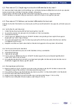
Страница 14: ... stabilise it 2 Using set point adjustment screw VG relax range spring RG until switch es C changes state 4 1 2 Checking Adjusting the set point 3 Slowly raise the pressure and then slowly lower it again Measure the lower and upper triggering thresholds 4 Fine tune the settings using adjustment screw VG Lower and Upper threshold control 5 Disconnect the instrument from the bench 6 Apply a seal to ...

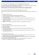
Страница 15: ... both chambers 10 bar and stabilise 2 Isolate both chambers 3 Create a pressure differential in favour of the HP chamber equal to the desired threshold value 1 bar HP 10 bar LP 9 bar 4 Using set point adjustment screw VG relax range spring RG until the exact point when switch es C is are triggered on the way up 5 Retighten and stop at the exact point where switch es C is are interlocked on the way...

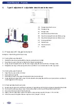
Страница 16: ...anges state 4 Retighten and stop at the exact point where switch es C is are interlocked on the way down 5 1 2 Setting the upper threshold 5 Keep the pressure stable at 2 mbar 6 Fully extend spring RE 7 Raise the pressure to the upper threshold 6 mbar and stabilise it 8 Using dead band adjustment screw VE relax dead band spring RE until the exact point when switch es C is are triggered on the way ...

Страница 17: ...bar 5 Using set point adjustment screw VG relax range spring RG until the exact point when switch es C is are triggered on the way up 6 Retighten and stop at the exact point where switch es C is are interlocked on the way down 5 3 2 Setting the upper threshold 7 Return to the desired static pressure in both chambers 10 bar and stabilise 8 Isolate both chambers 9 Fully extend spring RE 10 Create a ...

Страница 18: ...ax range spring RG until switch es C changes state 4 Retighten and stop at the exact point where the first threshold is triggered LP contact 6 1 2 Set the second HP switch threshold 5 Raise the pressure to the second threshold 6 bar and stabilise it 6 Fully extend spring RE 7 Using dead band adjustment screw VE relax dead band spring RE until the exact point when the second threshold HP switch is ...

Страница 19: ... Using set point adjustment screw VG relax range spring RG until the exact points when the two switches are triggered on the way up 6 Retighten until the exact point where the first threshold is triggered on the way down LP switches 6 3 2 Set the second HP switch threshold 7 Return to the desired static pressure in both chambers 10 bar and stabilise 8 Isolate both chambers 9 Fully extend spring RE...

Страница 20: ...nted according to the attached datasheet Apply graphite grease on the cable entry threading before tightening the cable gland Ensure that the cable gland has been tightened sufficiently and add drip protection to the cable in order to preserve the instrument s IP level 3 Internal terminal blocks The terminal blocks are designed for the following maximum wire size 2 5 mm for standard models and 1 5...

Страница 21: ... www georgin com The explosion proof switches with cable output must be imperatively connected to an approved terminal block and a junction box 4 2 Breaking capacity limits Gold plated contacts Minimum threshold Maximum threshold Never operate or test the instrument above the maximum threshold 18D and 20D 10 mA 6 Vdc 100 mA 24 Vdc 6D 34D 54D 4D 44D and 46D 1 mA 4 Vdc 100 mA 30 Vdc Other gold plate...

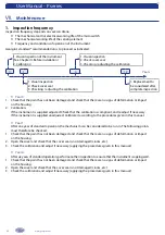
Страница 22: ...nstrument is supplied adjusted Check that the calibration is compliant and readjust if necessary If the instrument is supplied unadjusted Calibrate it according to the procedures given in this manual Year 1 After one year of standard operation the mechanism can be considered to be run in The following points must therefore be checked 1 Check that the paint has not been damaged and check that there...

Страница 23: ...rosive or crystalline fluid or environments Instruments in safety roles must be inspected annually 2 Precautions to take during maintenance The instrument must be disassembled WHEN DISCONNECTED FROM POWER using an appropriate spanner for the fitting GEORGIN guarantees the qualification of the equipment that leaves the factory Any operation performed on the equipment other than adjusting the instru...

Страница 24: ...el 33 0 1 46 12 60 00 Fax 33 0 1 47 35 93 98 Email regulateurs georgin com Belgium Temselaan 5 1st floor 1853 STROMBEEK BEVER Tel 32 0 2 735 54 75 Fax 32 0 2 735 16 79 Email info georgin be Designed developed and manufactured in France fu p en 11 01 2019 Subject to modifications due to technical advances ...

Отзывы: