GNX-10 Installation Guide
GenX Mobile, Incorporated
Version 1.01
Confidential and Proprietary
10/28/2004
All Rights Reserved
Page 1 of 1
(For Professional Installers Only)
Страница 1: ...GNX 10 Installation Guide GenX Mobile Incorporated Version 1 01 Confidential and Proprietary 10 28 2004 All Rights Reserved Page 1 of 1 GNX 10 Installation Guide For Professional Installers Only ...
Страница 2: ...d including interference that may cause undesired operation FCC RF Exposure Information Warning To satisfy the FCC RF exposure requirements a minimum separation distance of 20 cm must be maintained between the antenna and the operator The antenna supplied with this device must be used for installation and operation Substitution of other antennas must be approved by the manufacturer for compliance ...
Страница 3: ...formation On Board Low Power Motion Detector Enables services requiring long duration battery based operation Extended location coverage using on board accelerometers Dual Processors with Power Management Design Enables services requiring low power standby active operation such as battery powered security monitor operation 50 MIPS Main CPU Processing Capability Ample process throughput allows full...
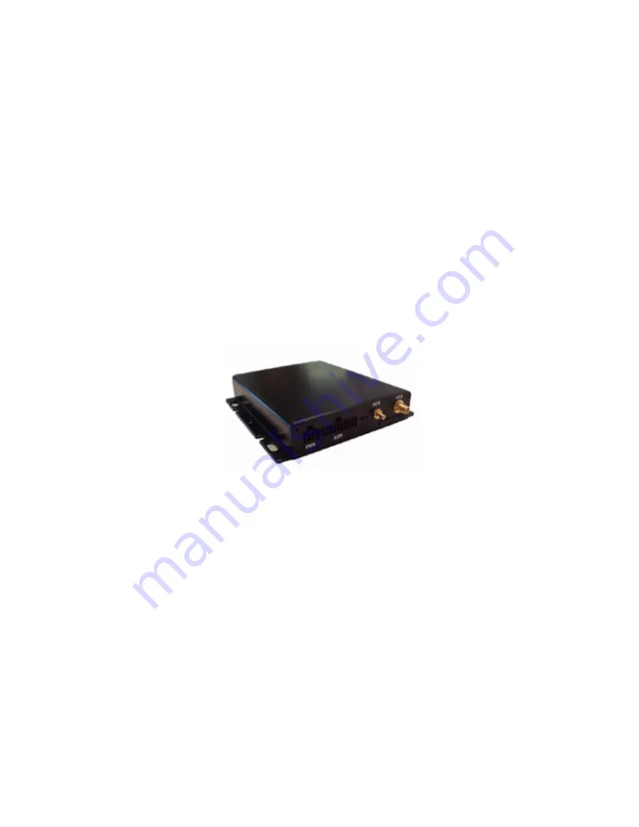
Страница 4: ...ty 5 to 95 non condensing Shock and Vibration SAE J1455 EMC EMI SAE J 1113 Processing capability 50 Mips equiv at full power Storage capacity Flash Memory 1M 8M Bytes NVSRAM 512k 4M Bytes Low power sensing mode All external input ports On board temperature sensor On board accelerometer Vehicle battery voltage monitor List of Input Output 1 10Base T Ethernet Port full NAT router 1 Serial Interface ...
Страница 5: ...ols Standard crimping tool not included Digital voltmeter Wire cutting tool Insulation tape Silicone Sealant for roof mount antennas only Optional flathead and Philips screwdrivers Optional butane soldering tool Optional power drill to create inch hole for roof mount antennas only GNX 10 Installation Contents Antenna Wiring harnesses Optional Ethernet adapter Wiring Harness Key Red Connect to 12V ...
Страница 6: ...ards end 3 INSPECT VEHICLE FOR DAMAGE Before installing do a thorough inspection of the interior and exterior of the vehicle noting any obvious vehicle damage Mark damage here Exterior Damage Dents Windshield cracks Chips Broken side mirrors Other Interior Damage Headliner rip Broken door handles Torn seats Other REPORT DAMAGE TO VEHICLE MANAGER OWNER 4 VERIFY VEHICLE OPERATION Verify normal vehic...
Страница 7: ... any covering around the steering column and use a digital voltmeter to identify wiring and voltage General guideline for Ford and GM vehicles White Stop Light Switch Green R R Lamp Yellow L R Lamp Purple Turn Signal Flasher Brown Flasher Dark Blue L F Lamp Light Blue R F Lamp Black Horn Orange Ignition Switch Dark Green Ground Tan Ground Red battery 12 V Again always check vehicle specifications ...
Страница 8: ...ggested locations Underneath steering column Underneath passenger side dash Behind radio Behind glove box Discrete trunk locations 2 Poke and Wrap After finding all relevant wiring sources strip wiring insulation accordingly to expose wires and connect wiring using a standard poke and wrap method Poke Use butane soldering iron or wire cutting tool to expose wires Poke wires from wiring harness thr...
Страница 9: ...the rear windshield Please note that the antenna should have a relatively clear view of the sky Please see diagram below for acceptable locations 4 Install Antenna Use standard 2 way radio antenna installation method for internal or glass mount antenna options For externally mounted roof mount antennas please use these guidelines Remove head liner where installation will take place Drill inch hole...
Страница 10: ...y Any RED light indicates a malfunction Please see key below for details GREEN DESCRIPTION OFF Power Down Mode FLASH Low Power Mode SLOW Full power Ignition OFF FAST Full Power Ignition ON RED DESCRIPTION OFF No faults detected 1 1 License Key Expired 2 1 GSM Module Fault 2 2 No SIM Inserted 2 3 No GSM Signal 2 4 Network not found 3 1 GPS Module Fault 3 2 GPS Antenna OPEN SHORT 3 3 GPS No Track 0 ...