September 2015
Service and Repair Manual
Manifolds
Part No. 1268515
Z-34/22 Bi-Energy
53
How to Adj ust the Secondary Boom Down R elief Valve
How to Adjust the Secondary
Boom Down Relief Valve
Note: Perform this procedure with the boom in the
stowed position.
Note: Refer to Function Manifold Component list to
locate the secondary boom down relief valve.
1 Connect a 0 to 5000 psi / 0 to 350 bar
pressure gauge to the test port on the function
manifold.
2 Move and hold the function enable toggle
switch to either side and hold the secondary
boom up/down toggle switch in the down
direction with the secondary boom fully
lowered.
3 Observe the pressure reading on the pressure
gauge. Refer to Specifications,
Hydraulic
Specifications
.
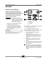
4 Turn the machine off. Hold the secondary
boom down relief valve with a wrench and
remove the cap.
5 Adjust the internal hex socket. Turn it
clockwise to increase the pressure or
counterclockwise to decrease the pressure.
Install the relief valve cap.
Tip-over hazard. Do not adjust
the relief valve higher than
specified.
6 Repeat steps 2 through 4 and recheck relief
valve pressure.
7 Remove the pressure gauge.
How to Adj ust the Tur ntabl e R otate R elief Valve
How to Adjust the Turntable
Rotate Relief Valve
Note: Perform this procedure with the boom in the
stowed position.
Note: Refer to Function Manifold Component list to
locate the turntable rotate relief valve.
1 Connect a 0 to 3000 psi / 0 to 200 bar
pressure gauge to the test port on the function
manifold.
2 Turn the key switch to ground control and pull
out the red Emergency Stop button to the on
position.
3 Move and hold the function enable toggle
switch to either side and move and hold the
turntable rotate toggle switch in the right
direction (until turntable stops against the
rotation stop). Observe the pressure reading
on the pressure gauge. Refer to
Specifications,
Manifold Component
Specifications.
4 Turn the machine off. Hold the turntable relief
valve(s) with a wrench and remove the cap.
5 Adjust the internal hex socket. Turn it
clockwise to increase the pressure or
counterclockwise to decrease the pressure.
Then install the relief valve cap.
Tip-over hazard. Do not adjust
the relief valve higher than
specified.
6 Repeat steps 2 and 3 to confirm the relief
valve pressure setting.
7 Remove the pressure gauge.
Содержание Z-22 Bi-Energy
Страница 63: ...September 2015 Service and Repair Manual Manifolds Part No 1268515 Z 34 22 Bi Energy 51...
Страница 87: ...September 2015 Service and Repair Manual 75 Electrical Schematic from serial number 4800 to 5426 ANSI CSA...
Страница 90: ...Service and Repair Manual September 2015 78 Electrical Schematic from serial number 4800 to 5426 ANSI CSA...
Страница 91: ...September 2015 Service and Repair Manual 79 Electrical Schematic from serial number 4800 to 5426 CE...
Страница 94: ...Service and Repair Manual September 2015 82 Electrical Schematic from serial number 4800 to 5426 CE...
Страница 95: ...September 2015 Service and Repair Manual 83 Electrical Schematic from serial number 5427 ANSI CSA...
Страница 98: ...Service and Repair Manual September 2015 86 Electrical Schematic from serial number 5427 ANSI CSA...
Страница 99: ...September 2015 Service and Repair Manual 87 Electrical Schematic from serial number 5427 CE...
Страница 102: ...Service and Repair Manual September 2015 90 Electrical Schematic from serial number 5427 CE...
Страница 103: ...September 2015 Service and Repair Manual 91 Ground Control Box Switch Panel Wiring Diagram...
Страница 106: ...Service and Repair Manual September 2015 94 Ground Control Box Terminal Strip Wiring Diagram...
Страница 107: ...September 2015 Service and Repair Manual 95 Platform Control Box Wiring Diagram...
Страница 110: ...Service and Repair Manual September 2015 98 Power Cable Wiring Diagram...
Страница 111: ...September 2015 Service and Repair Manual 99 Drive Contactor Panel Wiring Diagram...
Страница 114: ...Service and Repair Manual September 2015 102 Manifold and Limit Switch Wiring Diagram...
Страница 115: ...September 2015 Service and Repair Manual 103 LVI BCI Option Wiring Diagram from serial number 4800 to 5426...
Страница 118: ...Service and Repair Manual September 2015 106 LVI BCI Option Wiring Diagram from serial number 5427...
Страница 119: ...September 2015 Service and Repair Manual 107 Engine Wiring Diagram...
Страница 121: ...September 2015 Service and Repair Manual Part No 1268515 Z 34 22 Bi Energy 109 Hydraulic Schem atic Hydraulic Schematic...
Страница 123: ......

