background image

September 2015


Service and Repair Manual 


Specifications 


Part No. 1268515


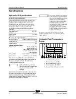
Z-34/22 Bi-Energy


Chevron Rando HD Premium Oil 

MV Fluid Properties 

ISO Grade 

32 

Viscosity index 

200 

Kinematic Viscosity 

cSt @ 200°F / 100°C 

cSt @ 104°F / 40°C 


7.5 

33.5 

Brookfield Viscosity 

cP @ -4°F / -20°C 

cP @ -22°F / -30°C 


1040 

3310 

Flash point 

375°F / 190°C 

Pour point 

-58°F / -50°C 

Maximum continuous operating 

temperature 

171°F / 77°C 

Note: An hydraulic oil heating system is 

recommended when the ambient temperature is 

consistently below 0°F / -18°C. 
Note: Do not operate the machine when the 

ambient temperature is below -20°F / -29°C with 

Rando HD Premium MV. 

Chevron 5606A Hydraulic Oil 

Fluid Properties 

ISO Grade 

15 

Viscosity index 

300 

Kinematic Viscosity 

cSt @ 200°F / 100°C 

cSt @ 104°F / 40°C 

cSt @ -40°F / -40°C 


5.5 

15.0 

510 

Flash point 

180°F / 82°C 

Pour point 

-81°F / -63°C 

Maximum continuous operating 

temperature 

124°F / 51°C 

Note: Use of Chevron 5606A hydraulic fluid, or 

equivalent, is required when ambient temperatures 

are consistently below 0°F / -17°C unless an oil 

heating system is used. 


Continued use of Chevron 

5606A hydraulic fluid, or 

equivalent, when ambient 

temperatures are consistently 

above 32°F / 0°C may result in 

component damage 

Petro-Canada Environ MV 46 

Fluid Properties 

ISO Grade 

46 

Viscosity index 

154 

Kinematic Viscosity 

cSt @ 200°F / 100°C 

cSt @ 104°F / 40°C 


8.0 

44.4 

Flash point 

482°F / 250°C 

Pour point 

-49°F / -45°C 

Maximum continuous operating 

temperature 

180°F / 82°C 

UCON Hydrolube HP-5046 Fluid 

Properties 

ISO Grade 

46 

Viscosity index 

192 

Kinematic Viscosity 

cSt @ 149°F / 65°C 

cSt @ 104°F / 40°C 

cSt @ 0°F / -18°C 


22 

46 

1300 

Flash point 

None 

Pour point 

-81°F / -63°C 

Maximum continuous operating 

temperature 

189°F / 87°C 


Содержание Z-22 Bi-Energy

Страница 1: ...from Z3414 9686 This manual includes Repair procedures Fault Codes Electrical and Hydraulic Schematics Bi Energy Power For detailed maintenance procedures refer to the appropriate Maintenance Manual...

Страница 2: ...defined by ISO 16368 Machine Design Life Unrestricted with proper operation inspection and scheduled maintenance Technical Publications Genie has endeavored to deliver the highest degree of accuracy...

Страница 3: ...sion History Revision Date Section Procedure Page Description A 9 2015 Release Reference Examples Electronic Version Click on any content or procedure in the Table of Contents to view the update Secti...

Страница 4: ...Service and Repair Manual September 2015 Introduction iv Z 34 22 Bi Energy Part No 1268515 Serial Number Legend 1 Model 2 Model year 3 Sequence number 4 Serial number stamped on chassis 5 Serial label...

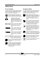
Страница 5: ...r serious injury Many of the hazards identified in the operator s manual are also safety hazards when maintenance and repair procedures are performed Do Not Perform Maintenance Unless You are trained...

Страница 6: ...l crushing hazards such as moving parts free swinging or unsecured components when lifting or placing loads Always wear approved steel toed shoes Workplace Safety Any person working on or around a mac...

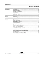
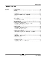
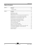
Страница 7: ...Rules v General Safety Rules v Section 2 Specifications 1 Machine Specifications 1 Performance Specifications 1 Hydraulic Specification 2 Hydraulic Component Specifications 4 Manifold Component Specif...

Страница 8: ...Leveling Slave Cylinder 17 How to Remove the Platform Leveling Slave Cylinder 17 How to Bleed the Leveling Slave Cylinder 17 2 2 Platform Rotator 18 How to Remove the Platform Rotator 18 How to Bleed...

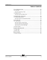
Страница 9: ...y Boom Extension Cylinder 30 How to Remove the Primary Boom Extension Cylinder 30 4 5 Platform Leveling Master Cylinder 31 How to Remove the Platform Leveling Master Cylinder 31 Secondary Boom Compone...

Страница 10: ...iliary Pump 47 How to Remove the Auxiliary Pump 47 8 2 Function Pump 48 How to Test the Function Pump 48 How to Removet the Function Pump 48 Manifolds 50 9 1 Function Manifold Components 50 9 2 Valve...

Страница 11: ...57 Turntable Rotation Components 59 11 1 Rotation Hydraulic Motor 59 How to Remove the Turntable Rotation Motor 59 Axle Components 60 12 1 Yoke and Hub 60 How to Remove the Yoke and Hub 60 How to Rem...

Страница 12: ...CE 80 Electrical Schematic from serial number 5427 ANSI CSA 84 Electrical Schematic from serial number 5427 CE 88 Ground Control Box Switch Panel Wiring Diagram 92 Ground Control Box Terminal Strip W...

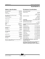
Страница 13: ...assification GL5 Performance Specificati ons Performance Specifications Drive speed maximum Stowed position 3 7 mph 5 9 km h 40 ft 7 5 sec 12 2 m 7 5 sec Raised or extended 0 6 mph 0 98 km h 40 ft 45...

Страница 14: ...tant UCON Hydrolube HP 5046 Note Genie specifications require additional equipment and special installation instructions for the approved optional fluids Consult Genie Product Support before use Optio...

Страница 15: ...t 104 F 40 C cSt 40 F 40 C 5 5 15 0 510 Flash point 180 F 82 C Pour point 81 F 63 C Maximum continuous operating temperature 124 F 51 C Note Use of Chevron 5606A hydraulic fluid or equivalent is requi...

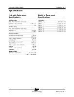
Страница 16: ...essure 3200 psi 220 6 bar Primary boom down relief function relief 1400 psi 96 5 bar Secondary boom down relief valve pressure 1600 psi 110 3 bar Primary boom extend relief valve pressure 1800 psi 124...

Страница 17: ...bs 515 Nm 280 ft lbs 379 Nm 3 8 16 outer bolts GR 8 dry 3 8 16 outer bolts GR 8 lubricated 44 ft lbs 60 Nm 33 ft lbs 45 Nm Turntable rotate assembly Rotate bearing mounting bolts lubricated 180 ft lbs...

Страница 18: ...l pressure 36 to 64 psi 2 48 to 4 41 bar Oil capacity including filter 2 6 quarts 2 5 liters Extreme operating temperatures may require the use of alternative engine oils For oil requirements refer to...

Страница 19: ...nerator pulley to engine pulley offset maximum 1 16 inch 1 6 mm Belt deflection maximum 1 4 inch 6 5 mm Generator Torque Specifications Generator pulley retaining nut torque 80 90 ft lbs 108 122 Nm En...

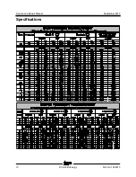
Страница 20: ...e Flats 4 7 16 20 2 6 9 16 18 1 8 3 4 16 1 10 7 8 14 1 12 1 1 16 12 1 16 1 5 16 12 1 20 1 5 8 12 1 24 1 7 8 12 1 SAE O ring Boss Port tube fitting installed into Aluminum all types SAE Dash Size Torqu...

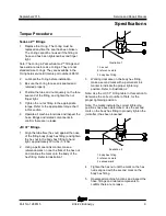
Страница 21: ...tings 1 Align the tube flare hex nut against the nose of the fitting body body hex fitting and tighten the hex nut to the body hex fitting to hand tight approximately 30 in lbs 3 4 Nm 2 Using a perman...

Страница 22: ...Service and Repair Manual September 2015 Specifications 10 Z 34 22 Bi Energy Part No 1268515 SAE and M etric Fasteners Tor que C harts...

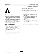
Страница 23: ...or s manual on your machine Be sure that all necessary tools and parts are available and ready for use Use only Genie approved replacement parts Read each procedure completely and adhere to the instru...

Страница 24: ...alert personnel to potential personal injury hazards Obey all safety messages that follow this symbol to avoid possible injury or death Indicates a imminently hazardous situation which if not avoided...

Страница 25: ...ion or assistance contact the Genie Product Support 1 boom function speed controller 2 drive joystick Boom Function Speed Contr oller Adj ustm ents Boom Function Speed Controller Adjustments Electrocu...

Страница 26: ...erclockwise to decrease the amperage 7 Turn the boom function speed controller to the 9 position 8 Set the max out Press down the foot switch and move the primary boom toggle switch to the down positi...

Страница 27: ...ove the bottom cover from the foot switch 2 Do not press down the foot switch Connect the leads from an ohmmeter or continuity tester to each wire combination listed on the next page and check for con...

Страница 28: ...ng from the toggle switch to be tested 2 Connect the leads of an ohmmeter to the switch terminals in the following combinations listed below to check for continuity Left Center Right SPDT DPDT Note Si...

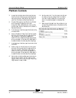
Страница 29: ...fer to Specifications Hydraulic Hose and Fitting Torque Specifications 1 Extend the boom until the slave cylinder barrel end pivot pin is accessible 2 Raise the boom slightly and place blocks under th...

Страница 30: ...a suitable lifting device Do not apply any lifting pressure 4 Remove the six mounting bolts from the platform mounting weldment Remove the center bolt and slide the platform mounting weldment off of t...

Страница 31: ...le switch to either side and hold the platform rotate toggle switch to the left position until the platform is fully rotated to the left Continue holding the toggle switch until air stops coming out o...

Страница 32: ...atform capacity at the center of the platform floor Determine the limit switch trigger point 4 Gently move the platform up and down by hand so it bounces approximately 1 to 2 inches 2 5 to 5 cm Allow...

Страница 33: ...indicator light and alarm turn off 8 Add an additional 10 lb 4 5 kg test weight to the original test weight to overload the platform Result The alarm should sound The platform overload indicator ligh...

Страница 34: ...ports T and P of the jib boom manifold Cap the fittings on the manifold Bodily injury hazard Spraying hydraulic oil can penetrate and burn skin Loosen hydraulic connections very slowly to allow the o...

Страница 35: ...n 7 Remove the jib boom bell crank from the extension boom Crushing hazard The jib boom bellcrank may become unbalanced and fall if it is not properly supported when it is removed from the machine 3 3...

Страница 36: ...ing strap from an overhead crane to the rod end of the jib boom lift cylinder 6 Remove the pin retaining fasteners from the jib boom lift cylinder barrel end pivot pin Use a soft metal drift to remove...

Страница 37: ...mary Boom 4 2 Primary Boom How to Shim the Primary Boom How to Shim the Primary Boom 1 Extend the boom until the wear pads are accessible 2 Loosen the wear pad mounting fasteners 3 Install the new shi...

Страница 38: ...oil pressure to dissipate gradually Do not allow oil to squirt or spray 9 Tag disconnect and plug the hydraulic hoses from the jib rotate manifold Bodily injury hazard Spraying hydraulic oil can penet...

Страница 39: ...refully remove the boom from the machine Crushing hazard If the overhead crane is not properly attached the boom could become unbalanced and fall when it is removed from the machine How to Disassembl...

Страница 40: ...y boom lift cylinder raises and lowers the primary boom The primary boom lift cylinder is equipped with a counterbalance valve to prevent movement in the event of a hydraulic line failure How to R emo...

Страница 41: ...1 Place a rod through the compression arm pivot pin and twist to remove the pin 12 Swing the compression arm up out of the way and secure it from moving 13 Tag disconnect and plug the primary boom lif...

Страница 42: ...g Torque Specifications 1 Raise the primary boom to a horizontal position Then extend the boom approximately 3 to 4 feet 1 m until the extension cylinder rod end pivot pins are accessible 2 Remove the...

Страница 43: ...form leveling master cylinder acts as a pump for the slave cylinder It is part of the closed loop hydraulic circuit that keeps the platform level through the entire range of primary boom motion The pl...

Страница 44: ...zard Spraying hydraulic oil can penetrate and burn skin Loosen hydraulic connections very slowly to allow the oil pressure to dissipate gradually Do not allow oil to squirt or spray 7 Tie a strap arou...

Страница 45: ...omponents Part No 1268515 Z 34 22 Bi Energy 33 Secondary Boom Component s Secondary Boom components 1 upper pivot 2 upper compression arm 3 mid pivot 4 compression link 5 lower secondary boom 6 turnta...

Страница 46: ...Remove the wire loom from the cables at the platform control box 6 Locate the four cables from the primary boom cable track to the platform control box Number each cable and its entry location at the...

Страница 47: ...the upper pivot to upper secondary boom pivot pin Use a soft metal drift to remove the pin 25 Carefully remove the entire primary boom assembly from the machine primary boom assembly jib boom assembl...

Страница 48: ...om the secondary boom lift cylinder Cap the fittings on the cylinder Bodily injury hazard Spraying hydraulic oil can penetrate and burn skin Loosen hydraulic connections very slowly to allow the oil p...

Страница 49: ...ft Cylinder The secondary boom lift cylinder raises and lowers the secondary boom The secondary boom lift cylinder is equipped with counterbalance valves to prevent movement in the event of a hydrauli...

Страница 50: ...the secondary boom enough to access the hydraulic hoses Do not pinch the hoses Component damage hazard Hoses can be damaged if they are kinked or pinched 8 Tag disconnect and plug the hydraulic hoses...

Страница 51: ...the Engine RPM 6 3 Engi ne Drive Pulley 6 3 Engine Drive Pulley How to R emove the Engi ne Drive Pulley How to Remove the Engine Drive Pulley 1 Remove the engine pivot plate latch retainer 2 Open the...

Страница 52: ...y bolt 6 shaft bushing 7 woodruff key How to Install the Engi ne Drive Pull ey How to Install the Engine Drive Pulley Note The generator pulley must already be installed before performing this procedu...

Страница 53: ...How to Remove the Engine Drive Pulley 6 4 C oolant Tem per ature and Oil Pressure Switches Coolant Temperature and Oil Pressure Switches The engine coolant temperature switch is a normally open switch...

Страница 54: ...then slide the pulley bushing off of the generator shaft 1 gap 2 shaft 3 set screw 4 engine drive pulley 5 engine drive pulley bolt 6 shaft bushing 7 woodruff key How to Install the Generator Pull ey...

Страница 55: ...y 2 Remove the engine pivot plate latch retainer 3 Open the engine pivot plate latch and swing the engine out away from the machine to access the generator belts 4 Loosen the tension adjustment bolt o...

Страница 56: ...circuits could result in death or serious injury Remove all rings watches and other jewelry 4 Start the engine from the ground controls and move the rpm select toggle switch to the maintained high idl...

Страница 57: ...e generator 6 Pull the generator away from the machine and remove the belts from the generator pulley 7 Remove the generator mounting fasteners then remove the generator from the machine 8 Remove the...

Страница 58: ...stall the new voltage regulator by following the previous steps in reverse order 18 Apply Loctite removable thread sealant onto the voltage regulator mounting fasteners and torque to specification Ref...

Страница 59: ...ground control and pull out the red Emergency Stop button to the on position at both the ground and platform controls 4 Activate any function using auxiliary power Result The pressure gauge reads 280...

Страница 60: ...nd and platform controls 4 Hold the function enable switch to either side and activate any boom function from the ground controls Result The pressure gauge reads 3000 psi 206 bar immediately stop The...

Страница 61: ...September 2015 Service and Repair Manual Part No 1268515 Z 34 22 Bi Energy 49 This page intentionally left blank...

Страница 62: ...it 25 30 ft lbs 34 41 Nm 9 Solenoid valve 3 position 4 way I Steer left right 10 12 ft lbs 14 16 Nm 10 3 position 4 way spool valve J Primary boom extend retract 10 12 ft lbs 14 16 Nm 11 Pressure swit...

Страница 63: ...September 2015 Service and Repair Manual Manifolds Part No 1268515 Z 34 22 Bi Energy 51...

Страница 64: ...r than specified 6 Repeat steps 2 through 4 and recheck relief valve pressure 7 Remove the pressure gauge How to Adj ust the Primary Boom Dow n R elief Valve How to Adjust the Primary Boom Down Relief...

Страница 65: ...eat steps 2 through 4 and recheck relief valve pressure 7 Remove the pressure gauge How to Adj ust the Tur ntabl e R otate R elief Valve How to Adjust the Turntable Rotate Relief Valve Note Perform th...

Страница 66: ...fold Components The jib boom platform rotate manifold is mounted to the jib boom Index No Description Schematic Item Function Torque 1 Solenoid valve 2 position 3 way CA Jib boom circuit 25 30 ft lbs...

Страница 67: ...nd disconnect the wiring from the coil to be tested 2 Test the coil resistance Coils with 2 terminals Connect the leads from the ohmmeter to the valve coil terminals Coils with 1 terminal Connect the...

Страница 68: ...to a terminal on the coil Resistor 10 Genie part number 27287 Note The battery should read 9V DC or more when measured across the terminals 1 multimeter 2 9V DC battery 3 10 resistor 4 coil Note Dott...

Страница 69: ...nting fasteners Note Clean the fuel tank and inspect for cracks and other damage before installing 10 2 Hydraulic Tank 10 2 Hydraulic Tank The primary functions of the hydraulic tank are to cool clean...

Страница 70: ...d drain the oil into a suitable container Bodily injury hazard Beware of hot oil Contact with hot oil may cause severe burns 5 Tag disconnect and plug the hydraulic hoses from the hydraulic tank filte...

Страница 71: ...connections must be torqued to specification during installation Refer to Specifications Hydraulic Hose and Fitting Torque Specifications Note Do not allow the turntable to rotate until the hydraulic...

Страница 72: ...lug nuts Do not remove them 3 Block the non steer wheels and then center a lifting jack under the steering axle 4 Raise the machine 6 inches 15 cm and place blocks under the drive chassis for support...

Страница 73: ...r and outer bearings including the pressed in races must be replaced 1 Be sure that both bearings are packed with clean fresh grease 2 Place the large inner bearing into the rear of the hub 3 Install...

Страница 74: ...n during installation Refer to Specifications Hydraulic Hose and Fitting Torque Specifications 1 Tag disconnect and plug the hydraulic hoses from the steering cylinder Cap the fittings Bodily injury h...

Страница 75: ...ations Hydraulic Hose and Fitting Torque Specifications 1 Remove the drive motor Refer to Repair Procedure How to Remove a Drive Motor 2 Disconnect and plug the hydraulic hose from the brake Remove th...

Страница 76: ...switch to the off position and disconnect the battery packs from the machine 2 Tag and disconnect all power cables from the motor controller Electrocution burn hazard Contact with electrically charge...

Страница 77: ...eels chocked All external AC power supply disconnected from the machine Boom in the stowed position Turntable secured with the turntable rotation lock Welder disconnected from the machine if equipped...

Страница 78: ...When adjusting the raised drive speed settings the maximum raised drive speed must not exceed 0 6 mph 1Km h or 40 feet 45 seconds 12 2 meters 45 seconds If the machine is allowed to drive faster than...

Страница 79: ...sition If problem persists replace the motor controller 1 Normal operation 12 HW FAILSAFE 1 2 3 Machine will not drive The motor controller failed self test Replace the motor controller 13 M SHORTED M...

Страница 80: ...rive joystick is defective Consult Genie Product Support 31 CONT DRVR OC Machine will not drive Main contactor PR1 coil defective OR brake release relay CR5 defective Replace main contactor PR1 or bra...

Страница 81: ...an 32V DC Completely charge batteries OR check battery cable condition OR check for corrosion or loose connections at battery terminals and motor controller 42 OVERVOLTAGE Machine will not drive Batte...

Страница 82: ...Service and Repair Manual September 2015 70 Z 34 22 Bi Energy Part No 1268515 This page intentionally left blank...

Страница 83: ...d obey the safety rules and operating instructions in the appropriate operator s manual on your machine Be sure that all necessary tools and test equipment are available and ready for use About This S...

Страница 84: ...nnection no terminal T circuits connect at terminal Circuits crossing no connection Quick disconnect terminal Circuit breaker with amperage Key switch Toggle switch DPDT Toggle switch SPDT Pump or Mot...

Страница 85: ...le valve 2 position 3 way Differential sensing valve Filter with bypass relief valve Relief valve with pressure setting Priority flow regulator valve Solenoid operated proportional valve Directional v...

Страница 86: ...Service and Repair Manual September 2015 74 Z 34 22 Bi Energy Part No 1268515 This page intentionally left blank...

Страница 87: ...September 2015 Service and Repair Manual 75 Electrical Schematic from serial number 4800 to 5426 ANSI CSA...

Страница 88: ...rvice and Repair Manual September 2015 76 Z 34 22 Bi Energy Part No 1268515 Electrical Schem atic from serial number 4800 to 5426 AN SI C SA Electrical Schematic from serial number 4800 to 5426 ANSI C...

Страница 89: ...September 2015 Service and Repair Manual Part No 1268515 Z 34 22 Bi Energy 77 Electrical Schematic from serial number 4800 to 5426 ANSI CSA...

Страница 90: ...Service and Repair Manual September 2015 78 Electrical Schematic from serial number 4800 to 5426 ANSI CSA...

Страница 91: ...September 2015 Service and Repair Manual 79 Electrical Schematic from serial number 4800 to 5426 CE...

Страница 92: ...Service and Repair Manual September 2015 80 Z 34 22 Bi Energy Part No 1268515 Electrical Schem atic from serial number 4800 to 5426 CE Electrical Schematic from serial number 4800 to 5426 CE...

Страница 93: ...September 2015 Service and Repair Manual Part No 1268515 Z 34 22 Bi Energy 81 Electrical Schematic from serial number 4800 to 5426 CE...

Страница 94: ...Service and Repair Manual September 2015 82 Electrical Schematic from serial number 4800 to 5426 CE...

Страница 95: ...September 2015 Service and Repair Manual 83 Electrical Schematic from serial number 5427 ANSI CSA...

Страница 96: ...Service and Repair Manual September 2015 84 Z 34 22 Bi Energy Part No 1268515 Electrical Schem atic from serial number 5427 AN SI C SA Electrical Schematic from serial number 5427 ANSI CSA...

Страница 97: ...September 2015 Service and Repair Manual Part No 1268515 Z 34 22 Bi Energy 85 Electrical Schematic from serial number 5427 ANSI CSA...

Страница 98: ...Service and Repair Manual September 2015 86 Electrical Schematic from serial number 5427 ANSI CSA...

Страница 99: ...September 2015 Service and Repair Manual 87 Electrical Schematic from serial number 5427 CE...

Страница 100: ...Service and Repair Manual September 2015 88 Z 34 22 Bi Energy Part No 1268515 Electrical Schem atic from serial number 5427 CE Electrical Schematic from serial number 5427 CE...

Страница 101: ...September 2015 Service and Repair Manual Part No 1268515 Z 34 22 Bi Energy 89 Electrical Schematic from serial number 5427 CE...

Страница 102: ...Service and Repair Manual September 2015 90 Electrical Schematic from serial number 5427 CE...

Страница 103: ...September 2015 Service and Repair Manual 91 Ground Control Box Switch Panel Wiring Diagram...

Страница 104: ...Service and Repair Manual September 2015 92 Z 34 22 Bi Energy Part No 1268515 Ground C ontrol Box Switch Panel Wiring Di agr am Ground Control Box Switch Panel Wiring Diagram...

Страница 105: ...September 2015 Service and Repair Manual Part No 1268515 Z 34 22 Bi Energy 93 Ground C ontrol Box Terminal Strip Wiring Di agr am Ground Control Box Terminal Strip Wiring Diagram...

Страница 106: ...Service and Repair Manual September 2015 94 Ground Control Box Terminal Strip Wiring Diagram...

Страница 107: ...September 2015 Service and Repair Manual 95 Platform Control Box Wiring Diagram...

Страница 108: ...Service and Repair Manual September 2015 96 Z 34 22 Bi Energy Part No 1268515 Platform C ontrol Box Wiring Di agr am Platform Control Box Wiring Diagram...

Страница 109: ...September 2015 Service and Repair Manual Part No 1268515 Z 34 22 Bi Energy 97 Pow er C abl e Wiring Diagram Power Cable Wiring Diagram...

Страница 110: ...Service and Repair Manual September 2015 98 Power Cable Wiring Diagram...

Страница 111: ...September 2015 Service and Repair Manual 99 Drive Contactor Panel Wiring Diagram...

Страница 112: ...Service and Repair Manual September 2015 100 Z 34 22 Bi Energy Part No 1268515 Drive Contactor Panel Wiring Diagram Drive Contactor Panel Wiring Diagram...

Страница 113: ...September 2015 Service and Repair Manual Part No 1268515 Z 34 22 Bi Energy 101 Manifold and Limit Swi tch Wiring Diagram Manifold and Limit Switch Wiring Diagram...

Страница 114: ...Service and Repair Manual September 2015 102 Manifold and Limit Switch Wiring Diagram...

Страница 115: ...September 2015 Service and Repair Manual 103 LVI BCI Option Wiring Diagram from serial number 4800 to 5426...

Страница 116: ...vice and Repair Manual September 2015 104 Z 34 22 Bi Energy Part No 1268515 LVI BCI Opti on Wiring Di agram from seri al num ber 4800 to 5426 LVI BCI Option Wiring Diagram from serial number 4800 to 5...

Страница 117: ...September 2015 Service and Repair Manual Part No 1268515 Z 34 22 Bi Energy 105 LVI BCI Opti on Wiring Di agram from seri al num ber 5427 LVI BCI Option Wiring Diagram from serial number 5427...

Страница 118: ...Service and Repair Manual September 2015 106 LVI BCI Option Wiring Diagram from serial number 5427...

Страница 119: ...September 2015 Service and Repair Manual 107 Engine Wiring Diagram...

Страница 120: ...Service and Repair Manual September 2015 108 Z 34 22 Bi Energy Part No 1268515 Engine Wiring Di agr am Engine Wiring Diagram...

Страница 121: ...September 2015 Service and Repair Manual Part No 1268515 Z 34 22 Bi Energy 109 Hydraulic Schem atic Hydraulic Schematic...

Страница 122: ...Service and Repair Manual September 2015 110 Hydraulic Schematic Z 34 22 Bi Energy Part No 1268515 Service and R epair M anual Sept ember 2015...

Страница 123: ......

Отзывы: