background image

3452535348

¤

Included Wall Control MUST be installed prior to operation of this Garage
Door Operator

Safe-T-Beam

®

Safety Reverse System Must be installed to close door

SAVE THIS MANUAL FOR FUTURE REFERENCE

NOTE: 

Your Residential Operator comes with a Rail Assembly which is

standard for up to a 7 foot 6 inch high door. An extension kit for an 8 foot

high door is available. 

®

®

For Answers and Assistance:

1.800.354.3643

or visit www.geniecompany.com

Series 

GCG, PCG, H

Includes                     Remote Control
and SERIES II Electronics

Garage Door

Operator 

Содержание Chain Glide Series GCG

Страница 1: ...SAVE THIS MANUAL FOR FUTURE REFERENCE NOTE Your Residential Operator comes with a Rail Assembly which is standard for up to a 7 foot 6 inch high door An extension kit for an 8 foot high door is avail...

Страница 2: ...rom obstruction and has a wood surface available for attaching the STB brackets The brackets may be attached to concrete if necessary but extra tools and special fasteners not supplied will be require...

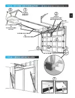
Страница 3: ...54 3643 OR GENIECOMPANY COM TYPICAL SUPPORT BRACKET EXTENSION SPRING OR TORSION SPRING SAFE T BEAM BRACES ADDED HEADER BRACKET MOUNTING BOARD TYPICAL 1 PIECE DOOR INSTALLATION 48 POWER CORD TO 120V GR...

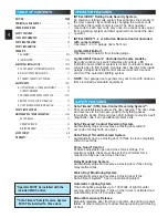
Страница 4: ...m inside garage Independent light control allows convenient manual control of the automatic lighting system NOTE Your garage door operator may not come with all above items included as standard equipm...

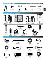
Страница 5: ...36 35 33 31 32 45 37 FASTENERS Shown Full Size See Parts List for description Lag screw 1 4 x 2 22 Screw 8 32 x 1 39 Self drilling Screw 1 4 20 x 3 4 42 Nut 1 4 20 10 Cotter pin 25 Clevis pin 24 Wire...

Страница 6: ...800 354 3643 OR GENIECOMPANY COM 2 3 PIECE RAIL HARDWARE EXPLODED VIEW 4 10 3 9 11 25 15 16 23 28 17 27 25 26 42 24 20 12 18 47 22 9 10 41 41 10 39 12 10 39 14 8 9 22 18 47 7 26 42 20 24 6 9 15 11 16...

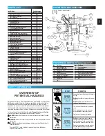
Страница 7: ...1E Circuit board assembly 1F Capacitor by series model 1G Opto wheel not shown 1H Carriage slide 1J Chain POWER HEAD PARTS LIST pre assembled Garage doors are large heavy objects that move with the he...

Страница 8: ...refer to the instruction sheet included with the optional rail extension at this point OPEN BLUE PARTS BAG 3 Attach rail clamps to rail Fig 1 3 Use pair of clamps at both joints Fasten each pair with...

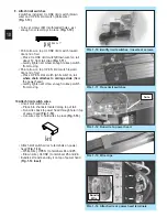
Страница 9: ...l to power head magnet Make sure that the carriage magnet is in place in the top of the carriage slide CAUTION 7 Attach emergency release cord knob and tag Tie overhand knot in 1 end of cord Tighten k...

Страница 10: ...Fig 1 10 Turn set screws 39 into threaded holes just enough so screw stays in place Fig 1 10 Point arrow on top CLOSE limit switch toward door end of rail Place CLOSE limit switch Brown wire on rail...

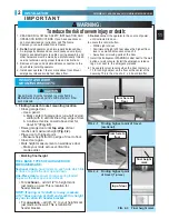
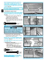
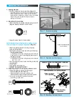
Страница 11: ...ntacts a 1 1 2 inch high object on the floor at the center of the doorway This is the size of a 2 x 4 board laid flat HEADER AND DOOR MOUNTING BRACKETS 1 Finding header bracket mounting location Close...

Страница 12: ...WER THAN top set of rollers Fig 2 7 For 1 piece doors door bracket must be mounted at top edge of door 4 Mounting the door bracket Proper bracing should be verified at this point Align door bracket ce...

Страница 13: ...door at highest point of travel b Be level or power head slightly below level Trackless doors a Rail must clear door at highest point of travel by 1 to 1 1 2 Securely tighten power head mounting bolt...

Страница 14: ...or arms sectional doors 27 28 INSTALL DOOR ARMS 1 piece doors OPEN YELLOW PARTS BAG 1 Attach the arms Straight arm to door bracket using clevis pin 24 and cotter pin 25 Fig 2 12 Curved arm to carriage...

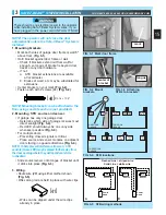
Страница 15: ...r Determine which side of garage receives most direct sunlight Fig 3 4 Red LED should always be on sunny side whenever possible Fig 3 4 For multiple doors Preventing crossed signals is critical Place...

Страница 16: ...the following Insure that no part of door or its hardware is in path between lenses of source and sensor Insure that tops of lenses are between 5 6 above the floor Fig 3 9 The brackets are flexible an...

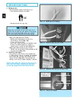
Страница 17: ...wall control to wall with 2 screws wall button use 33 console use 45 Fig 5 3 Remove protective backing from entrapment warning label Fig 5 4 Stick label on wall near wall control NOTE Additional wall...

Страница 18: ...ushing Connect permanent wiring to power head White to white black to black ground to green Use only UL recognized wire nuts Wires inside power head must be at least 6 in length Replace motor cover an...

Страница 19: ...g rail to align front edge of switch with back edge of carriage Fig 7 4 Gently tighten set screw Manually close door Place emergency release lever in engaged position Press wall control button Carriag...

Страница 20: ...erference to radio communications However there is no guarantee that interference will not occur in a particular installation If this equipment does cause harmful interference to radio or television r...

Страница 21: ...replacement Use coin ball point pen or similar device Gently push straight in on battery cover lock tab as shown Fig 9 1 Flip open battery cover Remove old battery Make sure new battery is facing pro...

Страница 22: ...l emergency release knob toward power head to place release lever in engaged position Operate door using remote Door will re attach itself to carriage assembly 3 Contact reverse Place a 2 x 4 board la...

Страница 23: ...repair properly lubricated and balanced See maintenance section Check OPEN limit switch setting See section Check OPEN FORCE adjustment See section Make sure carriage is engaged to carriage slide Plac...

Страница 24: ...ser diferentes a las reglamentaciones de los Estados Unidos y del Canad antes de usar los mismos Les metteurs sont conformes la r glementation am ricaine et canadienne compter de leur date de fabrica...

Страница 25: ...ot door Juego de extensi n deslizante Una extensi n de 18 pulgadas para aumentar la carrera de un abridor deslizable de cadena para acomodar una puerta de 8 pies 2 43 m N cessaire de rallonge du Chain...

Страница 26: ...nlit Perfect Stop GPS 5BL Stop Perfecto 00001200 04 00 Butoir Perfect Stop Chain Glide Extension Kit LCGX 8 Juego de extensi n de cadena deslizable 00001085 30 00 N cessaire de prolongement du couliss...

Страница 27: ...Name ____________________________________________________________________________ Dealer Address _________________________________________________________________________ City ________________________...

Страница 28: ...zas reemplazables la instalaci n el uso comercial los defectos resultantes de accidentes los da os mientras en tr nsito a nuestro lugar de servicio ni los da os resultantes de modificaciones del mal u...

Страница 29: ...__________________________ Mod le de la commande distance_____________________________________________________________ Nom du distributeur______________________________________________________________...

Страница 30: ...27 SCH MA DE CONNEXION DIAGRAMA DE CABLEADO...

Страница 31: ...pannage auto diagnostique du syst me STB afin de garantir un fonctionnement s curis N h sitez pas nous t l phoner pour tout probl me 1 800 354 3643 ou contacter www geniecompany com Usar el control de...

Страница 32: ...a cuerda de soltar con la puerta abierta Los resortes d biles o rotos pueden hacer que la puerta caiga r pidamente causando lesiones graves o la muerte 6 MANTENER LA PUERTA DEL GARAJE BIEN EQUILIBRADA...

Страница 33: ...courtiercuit vident teinte allum 1 absence de fils la source ou mauvaise connexion 2 lectricit aller interrompre 1 surveiller fils 2 eloigner electricit et rendre 1 signal clignotant pause se r p te a...

Страница 34: ...1 Ouvrir le couvercle de la pile Cubierta de bater a abierta FIG 8 2 Faire correspondre la polarit de la pile Hacer coincidir la polaridad de la bater a FIG 9 2 Fixer la lentille Apretar la lente FIG...

Страница 35: ...erador en un tomacorriente que est en circuito diferente al que est conectado el receptor Consultar con el distribuidor local TEST D INVERSION AU CONTACT Le r glage de la force et celui des but es de...

Страница 36: ...NCE COMPOSER LE 1 800 354 3643 OU VISITER NOTRE SITE GENIECOMPANY COM PARA AYUDA 1 800 354 3643 O GENIE COMPANY COM 6 AVERTISSEMENT FIG 6 1 Vis de r glage de la force Tornillos de ajuste de la fuerza...

Страница 37: ...ontr le mural jusqu ce que la porte soit compl tement ferm e Dans ce cas la t l commande ne fonctionnera pas NOTA Si existiera alg n problema con el STB que impida que la puerta cierre la puerta se pu...

Страница 38: ...NIE COMPANY COM 4 FIG 4 1 Connexion la t te motoris e Acoples de terminales a la caja de control FIG 4 2 Connexion la commande murale Acoplamiento de cables al control de pared FIG 4 3 Montage de la c...

Страница 39: ...B FIG 3 8 Connexion la t te motoris e Acoplamientos de terminales a la caja de control FIG 3 9 V rifier la hauteur des lentilles Verificar la altura de la lente ABRIR LA BOLSA ROJO DE PIEZAS 3 Cablead...

Страница 40: ...D tecteur Sensor Source Fuente Rouge rojo Verte verde T te Motoris e Caja de control A Ligne pointill e Fil ray Ligne continue Fil blanc FIG 3 4 Location de modules du STB Lugares del STB FIG 3 5 M th...

Страница 41: ...ras de la porte portes sections Acoplando los brazos de la puerta puertas seccionales FIG 2 12 Fixation des bras de la porte portes monopi ces Acoplando los brazos de la puerta puertas de una pieza 16...

Страница 42: ...O DESDE ARRIBA no est a escala 22 46 47 47 90 PORTE PUERTA PLACOPLTRE PARED SIN MORTERO 46 47 46 47 5 16 18 x 3 4 3 8 16 x 7 8 5 16 18 x 3 4 1 4 x 2 FIG 2 8 Placer le montage Posici n de montaje FIG 2...

Страница 43: ...Support de linteau en place 3 m thodes La cartela del travesa 3 m todos FIG 2 6 Exemples de renfort de porte Ejemplos de arriostramiento de la puerta FIG 2 7 Montage du support de porte sections Monta...

Страница 44: ...au centre de l ouverture de la porte Ceci quivaut une planche de 2 par 4 po pos e plat sur le sol FIG 2 1 Rep rage du point le plus lev de la course sections Encontrar el punto m s alto del recorrido...

Страница 45: ...tadores FIG 1 12 Passer le fil vers la t te motoris e Llevar los cables a la caja de control FIG 1 13 Pinces fil Grapas de cable FIG 1 14 Fixer le fil aux bornes de la t te motoris e Acoplar el cable...

Страница 46: ...edizo en el riel FIG 1 8 Attacher le cordon de d clenchement d urgence et l tiquette Acoplar la cuerda de soltar de emergencia y la etiqueta FIG 1 5 Fl ches d alignement Flecha de alineaci n FIG 1 7 F...

Страница 47: ...cci nes de riel 10 9 Premi re 1 4 20 1 4 20 x 5 8 ASSEMBLAGE DU RAIL Effectuer l assemblage sur une surface propre et plane Deuxi me Troisi me FIG 1 2 Fl ches d alignement Flechas de alineaci n FIG 1...

Страница 48: ...io capacitado usando las herramientas e instrucciones apropiadas RESORTE A ALTA TENSI N 1 tem Nombre de la pieza 1L M dulo motor 1M Regleta de terminales 1N Tornillo de cabeza hexagonal con arandela N...

Страница 49: ...hariot 1J Cha ne NOMENCLATURE DES PI CES DE LA T TE MOTORIS E Les portes de garage sont de gros objets lourds qui fonctionnent l aide de ressorts soumis une haute tension et de moteurs lectriques Dans...

Страница 50: ...CLAT E 4 Assemblage du rail 3 pi ces Conjunto de riel de 3 piezas 10 13 39 3 9 11 25 15 16 23 28 17 27 25 26 42 24 20 12 18 47 22 9 10 39 41 14 41 10 13 39 12 10 39 14 8 9 22 18 47 7 26 42 20 24 6 9 1...

Страница 51: ...a 24 Pince fil Grapa de cable ancho 41 Boulon 3 8 16 x 7 8 Perno 3 8 16 x 7 8 27 crou 3 8 16 Tuerca 3 8 16 28 Boulon 1 4 20 x 5 8 Perno 1 4 20 x 5 8 9 34 Console murale Consola de pared Bouton mural B...

Страница 52: ...la direcci n de una puerta cerr ndose dentro de los 2 segundos de contacto con un objeto El Sistema de inversi n cronizado Safe T Stop Autom ticamente abre y cierra la puerta si falla en cerrarse tota...

Страница 53: ...vant un contact avec un objet Syst me d inversion minut e Safe T Stop Ouvre automatiquement la porte qui se ferme si cette derni re ne se ferme pas compl tement dans les 30 secondes Commande Force Gua...

Страница 54: ...PUERTA DE 1 PIEZA T PICA CORDON ALIMENTATION 1 29m POUR PRISE TERRE DE 120V CORDON ALIMENTATION 1 29m POUR PRISE TERRE DE 120V BRIDE DE SUPPORT TYPE CARTELA DE APOYO T PICO TABL N DE MONTAJE DE CARTEL...

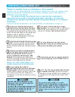
Страница 55: ...et la quincaillerie associ e subissent des tensions extr mes et peuvent entra ner des blessures voire la mort AVERTISSEMENT LISTA DE VERIFICACI N DE PREINSTALACI N PARA AYUDA 1 800 354 3643 O GENIE CO...

Страница 56: ...54 3643 ou visiter note site geniecompany com S ries GCG PCG et H T l commande et composants lectroniques de la S RIES II inclus El control de pared que se incluye DEBE instalarse antes de hacer funci...

Отзывы: