


Section 1 Introduction
1
st
Ed Nov 2018
IDU-450 EFIS Software Version 8.0H (Rotorcraft)
1-1
Section 1
Introduction
1.1. Introduction
Aviation has become more complex with sophisticated “automation
centered” systems, which minimize pilot involvement and automate control
of the aircraft and its systems, thereby relegating the pilot to the role of
manager and emergency backup.
The Genesys Aerosystems Electronic Flight Instrument System (EFIS) is
designed as a “pilot-centered” system. While still highly automated, it
presents the pilot with information necessary to make decisions and take
appropriate actions. For example, the Highway-in-the-Sky (HITS) allows for
highly automated approaches, but its predictive nature provides the pilot
awareness of upcoming maneuvers. Instead of overloading the pilot with
information and options, the Genesys Aerosystems EFIS presents only
necessary information to reduce workload, decrease task complexity, and
minimize confusion, which results in safer flying with less stress and
fatigue.
The Genesys Aerosystems EFIS goal is IFR-VFR equivalence with HUD
symbology overlaying real-time 3-D virtual view of the outside world. This
“synthetic vision” provides the pilot in IMC with simple visual clues for
navigation and aircraft control as those used in VFR conditions. The “virtual
VFR” eliminates the need to scan multiple instruments for aircraft control
or interpret complicated enroute and approach procedures. As experience
is gained with this integrated system, the pilot will fly with more precision,
awareness, and confidence.
1.2. EFIS/FMS
Description
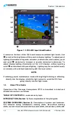
The integrated display unit (IDU) has eight buttons along the vertical sides
referenced as L1 through L4 starting at the top left corner of the display
moving down and R1 through R4 from the top right corner moving down
the display from a pilot’s perspective.
There are two encoders along the bottom. The left encoder (
) only
controls the backlighting intensity. References throughout this guide refer
to the right-hand encoder (
) and when to push and/or scroll for desired
outcomes.
On the bezel between the two encoders, a slip indicator or blank housing
acts as the USB memory door. When lifted prior to power-up, the ground
maintenance mode is initiated after power-up. If a limits change, software,
or database update is planned, the USB drive must be inserted prior to
power-up.