background image

26

Owner’s Manual for Mobile Light Tower

Troubleshooting

Troubleshooting the Lights

Only a qualified electrician should troubleshoot or repair electrical problems occurring in this equipment. Contact
Generac Mobile Technical Service at 1-800-926-9768 for assistance if you have any questions, or if problems persist.

(000278)

WARNING

Burn hazard. Lamps become extremely hot
while in use. Allow 10–15 minutes for cooling
before handling or lowering mast. Touching a 
hot lens or fixture can cause severe burns.

(000187)

WARNING

Electrocution. Potentially lethal voltages are generated
by this equipment. Render the equipment safe before
attempting repairs or maintenance. Failure to do so
could result in death or serious injury.

Lights Troubleshooting Guide

Problem

Possible Cause

Solution

Mast Lights OFF 
but ballast 
indicators on 
control panel ON

Light fixture is too hot.

Faulty lamp connection.

Lamp broken

Loose lighting 
connections 

Damaged or loose 
electrical cord

Allow light to cool 10-15 minutes before restarting.

Check that the lamp is tight in the socket.

Check for broken arc tube or outer lamp jacket, broken or loose 
components in lamp envelope, or blackening/deposits inside tube.

Check the connections inside the mast junction box and each mast light 
housing/socket.

Check the mast electrical cord for damage and check the cord connections 
inside the control box.

Mast Lights OFF 
and ballast 
indicators on 
control panel OFF

Loose lighting 
connections 

Generator output 
incorrect. 

Low transformer output. 

Check the connections inside the control box and inside each ballast box.

Check the incoming voltage to the ballast by checking the available voltage 
on the GFCI receptacle. Incoming voltage should be 120V +/- 5V. If voltage 
is incorrect, the engine speed may need to be adjusted or generator may 
require service.

The voltage from the transformer should read approximately 400VAC as 
the light “strikes” (induces an arc), then drop and slowly rise back up to 
stabilize at 240-260VAC. On hard wired models,
remove the mast junction box cover and insert the wire probes into the 
connector blocks for the light and ground. If proper voltage is not achieved, 
perform capacitor check to determine if the capacitor or coil needs
to be replaced.

Mast Lights ON but 
light output is low

Fixture and/or lens is 
dirty.

Lamp worn due to 
normal use

Damaged or loose 
electrical connections

Generator output 
incorrect. 

Low transformer output

Clean reflective surface inside fixture and both inside and outside surface 
of glass lens. Use mild soap and water to clean lens. Other chemicals may 
have an adverse effect on the glass.

Replace lamp.

Check the mast coil cord, mast junction box and mast light connections.

Check the incoming voltage to the ballast. Incoming voltage should be 
120V +/-5V. If the voltage is incorrect, the engine speed may need to be 
adjusted or the generator may require service.

The voltage from the transformer should read approximately 400VAC as the 
light “strikes” (induces an arc), then drop and slowly rise back up to stabilize 
at 240-260VAC. On hard wired models, remove the mast junction box cover 
and insert the wire probes into the connector blocks for the light and ground. 
If proper voltage is not achieved, perform capacitor check to determine if the 
capacitor or coil needs to be replaced.

Содержание MLT4060KV

Страница 1: ...al assistance contact www generacmobileproducts com Technical Service 1 800 926 9768 SAVE THIS MANUAL FOR FUTURE REFERENCE Owner s Manual Light Tower MLT4060MV MLT4060KV MLT4080KV SN ____________ and higher 004575 ...

Страница 2: ...ntenance for safe operation is performed promptly and to have the equipment checked periodically by a GMASD Normal maintenance service and replacement of parts are the responsibility of the owner or operator and as such are not considered defects in materials or workmanship within the terms of the warranty Individual operating habits and usage may contribute to the need for additional maintenance ...

Страница 3: ...ecklist 14 Raising the Mast 14 Starting the Unit 15 Automatic Shutdown 16 Light Operation 16 Voltage Regulator If Equipped 16 Auxiliary Outlets 17 Wet Stacking 17 Engine Derating 17 Shutting Down the Unit 17 Lowering the Mast 17 Lowering the Mast Manually 18 Towing the Unit 18 Lifting the Unit 19 Section 4 Maintenance Emissions Information 21 Daily Walk Around Inspection 21 General Maintenance 21 ...

Страница 4: ...iv Owner s Manual for Mobile Light Tower Trailer Lights Wiring 33 ...

Страница 5: ...products com parts service find service When contacting a GMASD about parts and service always supply the complete model number and serial number of the unit as given on its data decal located on the unit Record the model number and serial numbers in the spaces provided on the inside front cover of this manual Safety Rules The manufacturer cannot anticipate every possible circumstance that might i...

Страница 6: ...Failure to do so could result in death or serious injury 000105 DANGER Explosion and Fire Fuel and vapors are extremely flammable and explosive Add fuel in a well ventilated area Keep fire and spark away Failure to do so will result in death or serious injury 000147 WARNING Risk of Fire Unit must be positioned in a manner that prevents combustible material accumulation underneath Failure to do so ...

Страница 7: ...188 DANGER Electrocution Do not wear jewelry while working on this equipment Doing so will result in death or serious injury DANGER Electrocution DO NOT use the unit if electrical cord is cut or worn through Doing so will result in death or serious injury 000263a 000188 DANGER Electrocution Do not wear jewelry while working on this equipment Doing so will result in death or serious injury 000137a ...

Страница 8: ...ng Ambient air temperature is above 120 F 49 C Operating Safety Positioning the Unit The area immediately surrounding the unit should be dry clean and free of debris Position and operate the unit on a firm level surface If the unit is equipped with a frame grounding stud follow the National Electrical Code NEC state and local guidelines when connecting Starting the Unit 000192 DANGER Explosion and...

Страница 9: ...tions and warn of dangers and hazards Wear heavy leather gloves when handling winch cables Never let cables slip through bare hands Only use mild soap and water to clean the lens covers Other chemicals may damage the lens covers Make sure slings chains hooks ramps jacks and other types of lifting devices are attached securely and have enough weight bearing capacity to lift or hold the equipment sa...

Страница 10: ... connected and working properly Wheels and Tires Check trailer tires for wear and proper inflation Verify wheel lug nuts are present and tightened to the specified torque Safe Towing Techniques Practice turning stopping and backing up in an area away from heavy traffic prior to transporting the unit Maximum recommended speed for highway towing is 45 mph 72 km h Recommended off road towing speed is...

Страница 11: ...ter qt L 5 0 4 7 5 4 5 1 5 4 5 1 Generator Make Model Marathon Electric 201CSA5411 Marathon Electric 201CSA5411 Marathon Electric 201CSA5420 Type Insulation Brushless F Brushless F Brushless F Output kW kVA 6 0 6 0 6 0 6 0 8 0 8 0 Output Voltage V 120 240 single phase 120 240 single phase 120 240 single phase Output Amperes 120V 240V A 50 25 50 25 66 33 Frequency Hz 60 60 60 Power Factor 1Ø 1 1 1 ...

Страница 12: ...nual for Mobile Light Tower General Information Unit Dimensions Figure 2 1 Unit Dimensions MLT4060MV MLT4060KV MLT4080KV A B C D E 115 in 2 92 m 107 in 2 71 m 25 ft 7 6 m 68 in 1 73 m 140 in 3 56 m A B C E D 004586 ...

Страница 13: ...Manufactured by Generac Mobile Products LLC 920 361 4442 800 926 9768 VIN Tag TIRE AND LOADING INFORMATION RENSEIGNEMENTS SUR LES PNEUS ET LE CHARGEMENT SEE OWNER S MANUAL FOR ADDITIONAL INFORMATION VOIR LE MANUEL DE L USAGER POUR PLUS DE RENSEIGNEMENTS MANUFACTURED BY FABRIQUE PAR Generac Mobile Products LLC DATE 00 0000 GVWR PNBV 000KG 0000LBS COLD INF PRESS PRESS DE V I N N I V 0000000000000000...

Страница 14: ...ent Locations A Engine exhaust G Mast rotation knob B Mast switch H Fuel fill inside unit C Forklift pockets I Outriggers D Battery inside unit J Engine access door E Control box inside unit K Radiator access panel top of unit F Central lift point LEFT SIDE RIGHT SIDE 004589 A B C D E F C G H I J K ...

Страница 15: ...for service G DC Circuit Breaker Circuit breaker 10A for the engine electrical system H 240V Twist Lock Outlet This 240V 30A outlet supplies power for accessories connected to the generator when the engine is running and the main circuit breaker is switched ON I I 120V GFCI Outlets This 120V 20A GFCI outlet supplies power for accessories connected to the generator when the engine is running and th...

Страница 16: ...ours for service H DC Circuit Breaker Circuit breaker 10A for the engine electrical system I 240V Twist Lock Outlet This 240V 30A outlet supplies power for accessories connected to the generator when the engine is running and the main circuit breaker is switched ON I J 120V GFCI Outlet 2 Locations This unit 120V 20A GFCI outlet supplies power for accessories connected to the generator when the eng...

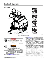
Страница 17: ...the trailer tongue For grounding requirements follow the National Electrical Code NEC state and local regulations 5 Pull the locking pins D on the outriggers E and pull each outrigger out until the spring loaded locking pin snaps back into place Pull the locking pin on each outrigger jack and rotate each jack 90 so the jack pad is facing down and the spring loaded locking pin snaps back into place...

Страница 18: ...FF O position Verify all circuit breakers are in the OFF O position Inspect all electrical cords repair or replace any that are cut worn or bare Verify all winch cables are in good condition and centered on each pulley Do not use if cables are kinked or beginning to unravel Check oil coolant and fuel levels For more information refer to General Maintenance Verify battery connections are secure Tur...

Страница 19: ...he glow plug indicator turns red Kubota units do not have a glow plug indicator Figure 3 4 Activate Glow Plug 3 See Figure 3 5 Turn the key to the right START position and hold it until the engine cranks and starts running NOTE For cold weather conditions refer to the engine operator s manual for appropriate glow plug interval NOTE If oil pressure is not obtained within 15 seconds after the key is...

Страница 20: ...uire a warm up period of 5 15 minutes before they reach full output If the lights are shut down they require a cool down period of approximately ten minutes before they can be switched on again NOTE The light tower uses four 1100W bulbs When checking or replacing the bulbs wipe them with a clean cloth to avoid leaving any grease oil residue or fingerprints on the glass Any residue can create a hot...

Страница 21: ...ture Derating reduces the available power for operating tools and accessories connected to the outlets For every increase in 1000 ft 305 m of elevation engine performance for this unit typically drops between 2 and 4 Also engine performance decreases about 1 for every 10ºF 5 6ºC increase in ambient air temperature over 72ºF 22ºC Shutting Down the Unit Check with personnel using power supplied by t...

Страница 22: ...and release the jack locking pin to swing the jacks up into the travel position Verify the locking pins snap into place Release the outrigger locking pins and slide the outriggers into the trailer frame until the locking pins snap into place 3 Use the tongue jack to raise or lower the trailer onto the hitch of the towing vehicle Lock the hitch coupling and attach the safety chains or cables to the...

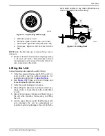
Страница 23: ...ment being used to lift the unit is in good condition and has sufficient capacity For approximate weights refer to Specifications 2 See Figure 3 12 Close and lock all hoods and doors and stow the lights as shown 3 Verify the cradle locking pin is in place 4 When lifting the light tower and trailer attach any slings chains or hooks directly to the central lifting eye A 5 Always remain aware of peop...

Страница 24: ...20 Owner s Manual for Mobile Light Tower Operation This page intentionally left blank ...

Страница 25: ...e the emissions warranty Preparing for Service Before servicing the unit always follow the instructions listed below 1 Verify the Control Power switch is in the OFF O position 2 Verify the circuit breakers are switched OFF O 3 Disconnect the negative terminal on the battery 4 Attach a Do Not Start sign to the control panel This will notify everyone that the unit is being serviced and will reduce t...

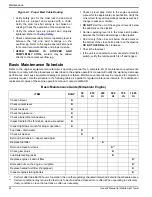
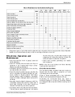
Страница 26: ... switch is off and tagged Basic Maintenance Schedule Refer to the original equipment manufacturer s operating manual for a complete list of maintenance requirements Failure to comply with the procedures as described in the engine operator s manual will nullify the warranty decrease performance and cause equipment damage or premature failure Maintenance records may be required to complete a warrant...

Страница 27: ...abor or get excessively hot during the lowering of loads the brake will need to be serviced or replaced Check motor brushes periodically and replace when necessary NOTE Only the motor brushes and brake assembly require periodic replacement Winch Mechanical Brake The mechanical brake generates heat when loads are lowered and the wire cable is powered out Avoid overheating the mechanical brake Whine...

Страница 28: ...d pump grease into the fitting until new grease is visible around the nozzle of the grease gun Use only a high quality grease made specifically for lubrication of wheel bearings Wipe any excess grease from the hub with a clean cloth and replace the rubber plug when finished The minimum recommended lubrication is every 12 months or 12 000 miles 19 312 km more frequent lubrication may be required un...

Страница 29: ...ine Visually inspect the engine for leaks Oil pressure switch failure Refer to OEM engine operator s manual to identify corrective action High coolant temperature shutdown Low coolant level Add coolant if needed Allow engine to cool then check coolant level in radiator Restart engine and check coolant temperature Stop engine immediately if coolant temperature is 210 F 99 C or more Blockage in radi...

Страница 30: ...rol box and inside each ballast box Check the incoming voltage to the ballast by checking the available voltage on the GFCI receptacle Incoming voltage should be 120V 5V If voltage is incorrect the engine speed may need to be adjusted or generator may require service The voltage from the transformer should read approximately 400VAC as the light strikes induces an arc then drop and slowly rise back...

Страница 31: ...Owner s Manual for Mobile Light Tower 27 Section 6 Wiring Diagrams Mast Junction Box Wiring and Light Connections 00768 1 3 2 4 ...

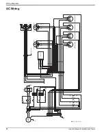
Страница 32: ...T GN 8KW UNITS ONLY 8KW UNITS ONLY 1 GN WT 3 GN WT BK 2 GN WT BK 4 GN WT BK BK 20A 30A RD RD BK BK BK BK WT GN RD YL RD BK BL WT YL RD BK BL BK RD GY RD RD RD RD RD RD GY GY BK BK BL BL BK RD YL RD BK BK RD RD BK RD BK CAP 2 CAP 1 CAP 3 CAP 4 TRANSFORMER 1 TRANSFORMER 2 TRANSFORMER 3 TRANSFORMER 4 GN GN WT WT 20A RD RD BK BK BK BK BL BK RD YL BK RD YL BK RD YL WT WT WT WT WT WT 15 A 15 A 15 A 15 A...

Страница 33: ...Owner s Manual for Mobile Light Tower 29 Wiring Diagrams DC Wiring Mitsubishi 10000044660_B_02 07 19 ...

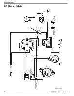
Страница 34: ... VI YL BK WT BK WT RD BK FUEL PUMP 10 AMP CIRCUIT BREAKER OIL PRESSURE WARNING SWITCH N C SWITCH N O WARNING OVERHEAT 12V BATTERY STARTER RELAY TIME DELAY GY BL GY VI RD RD BK BK YL GLOW PLUGS AUX SWITCH MAIN BREAKER RD VI ALTERNATOR WARNING LIGHT TURN MAIN BREAKER OFF BK WT BK RD YL OR YL RD VI RD VI N C N O COM RD VI YL BK 90339_E_01 30 14 ...

Страница 35: ...Owner s Manual for Mobile Light Tower 31 Wiring Diagrams DC Wiring Electric Winch ...

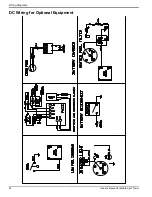
Страница 36: ...32 Owner s Manual for Mobile Light Tower Wiring Diagrams DC Wiring for Optional Equipment ...

Страница 37: ...ER TRAILER PLUG RIGHT TAIL TURN LAMP LAMP PLATE LICENSE MARKER LAMP RED BK BK BK BK RD WT BK SPLICE SPLICE SPADE SPADE LAMP TAIL TURN LEFT RD WT BK SPADE YL BN WT SPADE SPADE WT BK BN WT SPLICE GN RING MARKER LAMP AMBER MARKER LAMP RED BK BK BK BK SPLICE SPLICE SPADE SPADE BN WT WT WT BN BN 90341_B_12 20 13 ...

Страница 38: ...34 Owner s Manual for Mobile Light Tower Wiring Diagrams This page intentionally left blank ...

Страница 39: ......

Страница 40: ...eProducts com 800 926 9768 920 361 4442 Part No 33298 Rev F 01 14 2020 2020 Generac Mobile Products LLC All rights reserved Specifications are subject to change without notice No reproduction allowed in any form without prior written consent from Generac Mobile Products LLC ...

Отзывы: