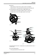
Fig.68
Fig.69
Pneumatic block (8.2) for max. 1 solenoid valve / pneumatic block (8) for max. 3
solenoid valves
Hint!
When using the pneumatic block (8.2) with one control plate (65), the
groove (65.12) must be fitted on the left side. The two screws (66) are
located in the left mounting holes.
When using the pneumatic block (8) with 1 or 2 control plates (65), the
groove (65.22) must be mounted upward. The screws (66) are located
in the lower mounting holes.
On ASEPTOMAG valves, special types of the pneumatic block must be used!
Tighten the screws (66) to a max. tightening torque of 1 Nm.
10.4.4 Removing the logic element NOT (seal pack)
Requirement:
•
Logic element NOT is only provided in connection with the pneumatic block
T.VIS/NOT!
Carry out the following steps:
1.
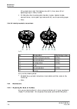
Loosen the screws (67) and remove logic element NOT (64) with flat gasket
and adapter plate (64.1).
Maintenance
Dismantling the Control Top into its Components
430BAL010697EN_2
15.04.2020
97
Содержание T.VIS M-15
Страница 6: ...430BAL010697EN_2 6 15 04 2020...
Страница 53: ...Fig 27 Assembly and installation Electrical connections 430BAL010697EN_2 15 04 2020 53...
Страница 55: ...Fig 28 Assembly and installation Electrical connections 430BAL010697EN_2 15 04 2020 55...
Страница 111: ...14 Spare parts list Switch bar T VIS M 15 Fig 82 Spare parts list Switch bar T VIS M 15 430BAL010697EN_2 15 04 2020 111...
Страница 119: ...Appendix 430BAL010697EN_2 15 04 2020 119...
Страница 120: ......


