


D
GB
F
E
I
Ru
27
09637-06.2015-DGbFEIRu
9
|
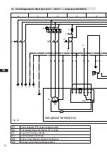
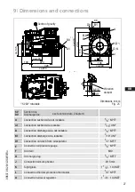
Dimensions and connections
SV
DV
Suction line
Discharge line see technical data, Chapter 8
A
Connection suction side, not lockable
1/8“ NPTF
A1
Connection suction side, lockable
7/16“ UNF
B
Connection discharge side, not lockable
1/8“ NPTF
B1
Connection discharge side, lockable
7/16“ UNF
D1
Connection oil return from oil separator
1/4“ NPTF
E
Connection oil pressure gauge
1/8“ NPTF
F
Oil drain
M10
H
Oil charge plug
1/4“ NPTF
J
Connection oil sump heater
Ø 15 mm
K
Sight glass
1 1/8“- 18 UNEF
L
Connection thermal protection thermostat
1/8“ NPTF
O
Connection oil level regulator
1 1/8“- 18 UNEF
Dimensions in mm
Fig. 25
Vibration
damper
1)
SV 90° rotatable
ca.115
ca.
135
Schwingungsdämpfer
Vibration absorbers
Amortisseurs de vibration
40
30
M10
A1
SV
328
223
109
ca.470
14430
14441
HGX22P/125-4 14433
14434
HG22P/160-4 S
HGX22P/160-4 S
14437
Typ
HG22P/125-4 S
Teile Nr.
14436
HGX22P/190-4 S
14432
Typ
HGX22P/190-4
HGX22P/125-4 S 14439
HG22P/190-4
Teile Nr.
14438
HG22P/160-4
14440
14431
HG22P/190-4 S
HGX22P/160-4
Typ
14435
Typ
Teile Nr.
Teile Nr.
HG22P/125-4
Anschlüsse
Connections
Raccords
SV Saugabsperrventil, Rohr (L)*
Suction line valve, tube (L)*
Vanne d’arrêt d’aspiration, de tuyau (L)*
mm - Zoll
22 – 7/8 “
DV Druckabsperrventil, Rohr (L)*
Discharge line valve, tube (L)*
Vanne d’arrêt de refoulement, de tuyau (L)* mm - Zoll
16 - 5/8 “
A Anschluß Saugseite, nicht absperrbar
Connection suction side, not lockable
Raccord côté aspiration, non obturable
Zoll
1/8“ NPTF
A1 Anschluß Saugseite, absperrbar
Connection suction side, lockable
Raccord côté aspiration, obturable
Zoll
7/16“ UNF
B Anschluß Druckseite, nicht absperrbar
Connection discharge side, not lockable
Raccord côté refoulement, non obturable
Zoll
1/8“ NPTF
B1 Anschluß Druckseite, absperrbar
Connection discharge side, lockable
Raccord côté refoulement, obturable
Zoll
7/16“ UNF
D1 Anschluß Ölrückführung vom Ölabscheider Connection oil return from oil separator
Raccord retour d’huile du séparateur d’huile
Zoll
1/4“ NPTF
E Anschluß Öldruckmanometer
Connection oil pressure gauge
Raccord du manomètre de pression d’huile
Zoll
1/8“ NPTF
F Ölablaß
Oil drain
Vidange d’huile
mm
M10
H Stopfen Ölfüllung
Oil charge plug
Bouchon de remplissage d’huile
Zoll
1/4“ NPTF
J Ölsumpfheizung
Oil sump heater
Chauffage du carter d’huile
mm
15
K Schauglas
Sight glass
Voyant
Zoll
1 1/8 “ – 18 UNEF
L Anschluß Wärmeschutzthermostat
Connection thermal protection thermostat Raccord de thermostat de protection thermique
Zoll
1/8“ NPTF
O Anschluß Ölspiegelregulator
Connection oil level regulator
Raccord régulateur de niveau d’huile
Zoll
1 1/8 “ – 18 UNEF
(L)* = Lötanschluß
(L)* = Brazing connection
(L)* = Raccord à braser
Änderungen vorbehalten
Dimensions in mm
Sous réserve de toutes modifications
Maße Zubehör / Dimensions Accessories / Dimensions Accessoires
Subject to change without notice
1.0850-14438.0 n
Cotes en mm
Maße in mm
Halbhermetischer Verdichter HG / Semi-hermetic compressor HG / Compresseur semi-hermétique HG
Massenschwerpunkt
Centre of gravity
Centre de gravité
ca.515
Rz 63
Rz 6,3
Maßstab:
%
F
E
D
C
B
A
F
E
D
C
CA
D-
Ze
ic
hnung
- Da
rf
nur
ma
sc
hine
ll g
eä
nde
rt
w
er
de
n.
4
3
2
1
A
B
5
6
7
8
1
2
3
4
5
6,3
über 0.5
8
Zeichn.-Nr. / Drawing no. /
Numéro de plan:
Tol.-Ang. DIN ISO 2768-mK
1
R
ev
is
io
ns
dur
chl
auf
:
Transportwinkel geändert / Betrifft Blatt 2
Rz 160
Ra Rz
s
25
Betrifft Blatt 3 - BS-Befestigungsteile
Maß
Passung
Freigabe
Alternativbezug:
Baumustergeprüft
Teil inaktiv
Lieferantenzeichnung
-
-
K.-Auftrag:
PL:
Zeichnung ungültig
Entwicklungsstand
Teil keine Serie
120
400
±0.5
bis 6
Benzstraße 7 - 72636 Frickenhausen - Germany - www.bock.de
Layh
Layh
Layh
Layh
Schaich
Büttner
Schni
Buck
Bau
Bau
18.11.09
23.06.09
15.09.08
21.11.07
14.05.07
7601, 7624
7430,7466,7519,7531,7539
7341,7367,7375
7022,7090,7176.7181
7040 / 7061
-
-
-
-
-
Betrifft Bl.2+3
Betrifft Bl.2+3
Betrifft nur Blatt 2+3
Div. Änderungen (Betrifft Bl. 2+3)
n
m
l
k
j
i
-
Layh
Franke
20.06.06
6756
-
h
-
Unbemaßte Radien:
-
z
y
x
6
Rz 16
Rz 25
2
1,6
Rz 12,5
0,7
0,3
7
u
t
an dieser Zeichnung vor.
Bearb.
Datum
Änderungs-Nr.
Werkstoff:
Ausgangsteil, bzw. Rohteil:
-
-
Gepr.
Name
Datum
22.07.
04.12.
0,05 Rz 1,6
Werkstückkanten
DIN ISO 13715
Ersatz für:
Ersetzt durch:
Erstellt
2006
Geprüft
14438.0g
Layh
Bauknecht
Zone
1/3
Oberflächenbehandlung / Härte:
-
Blatt:
Änderungsbeschreibung
400
Benennung:
±0.8
1000
30
6
-
±0.3
120
30
±0.2
Zeichn.-Nr. Teile-Nr.
Oberflächenangaben
nach DIN ISO 1302
1.0850-14438.0
Zust.
Gußtoleranzen:
Gewicht: (kg)
±0.1
w
7341: Schwerpunkt eingetragen, 7375, 7367: Betrifft nur Blatt 2
-
7291
02.06.08 Büttner
Layh
Diese Zeichnung ist unser Eigentum!
Sie darf ohne unsere Genehmigung weder nach-
gebildet, vervielfältigt, oder Dritten Personen zu-
gänglich gemacht werden. Der Nachbau nach
dieser Zeichnung, oder an Hand der nach dieser
Zeichnung hergestellten Gegenstände durch den
Abnehmer oder Dritte ist nicht gestattet.
Wir behalten uns alle Rechte, gemäß DIN ISO 16016
HG22P/190-4 S
A
O,K
B,L
DV
F
J
H,D1
E
B
B1
88
198
115
264
ca.240
4x 12
ca.310
ca.350
ca.
595
1)
Centre of gravity