


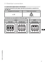
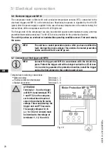


D
GB
F
E
I
Ru
19
09791-01.2015-DGbFEIRu
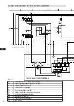
M1
Compressor motor
M1.1
Fan motor
K1
Mains contactor
K2
Δ
-contactor
K3
Y-contactor
K4T
Delay relay S/D changeover
K5T
Delay relay, start unloader
S1
Control voltage switch
AL
Start unloader
E1
Oil sump heater
nderung
0
Datum
Name
Datum
Bearb.
Gepr.
Norm
1
20.Feb.2009
Kelich
10.Feb.2010
Urspr.
2
Ers.f.
3
Ers.d.
4
D/S
MP10
5
6
7
BOCKCOMPRESSORS
8
=
+
9
Bl.
1
Bl.
1
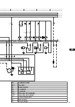
XSS
Q1
L1
L2
L3
Net400V50Hz
N
PE
F1.1
K1
1
2
F1.2
1
AnschluákastenVerdichter
3
4
2
5
6
3
U1
V1
W1
M
3
~
M1
Y
K3
1
2
R1
3
4
5
6
W2
U2
V2
D
K2
1
2
4
3
4
5
5
6
6
PE
X1 L1 L1 N N 43 43 11
12
14
L
S
M
X2 1 2 3 4 5 6
F1.1
F1.2
R2
4A
F2
S1
7
MP10
8
9
X3
1
M
~
1
M1.1
10
2
K1
11
3
C1
4
F5
K1
K1
T2
K3
P>
F3
N
P™l
K4T
K3
K2
L
12
M
K4T
K2
K3
13
S
14
K4T
P
F4
15
K5T
AL
16
17
K5T
P<
B1
18
19
K1
20
E1
21
L1.1
L2.1
L3.1
L1.2
N
PE