background image

Grasso

Refrigeration Division

GRASSO SYSTEM CONTROL

01.2002/ 0

638660E_chapter4.doc

Chap. 4 - 3

4.3


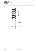
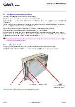
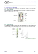
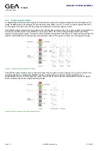
Meaning of the key-operated switches

SF-DP
(red)

Meaning 

Remedy

RUNP
(R-P)

The C7 CPU processes the application program.
The program and data can:

- be read out of the C7-CPU with the PG (C7 

Æ

 PG)

- be transferred into the C7-CPU or be amended there (PG 

Æ

 C7)

RUN
(R)


or 


The C7 CPU processes the application program.
The programs and data can:

- be read out from the C7 CPU using the PG (C7 

Æ

 PG)

- not be transferred to the C7 CPU or be amended there (PG 

Æ

 C7)

STOP
(S)

The C7 CPU does not edit the application program.
Programs can:

- be read out of the C7 CPU using the PG (C7 

Æ

 PG)

- be transferred to the C7 CPU or be amended there (PG 

Æ

 C7)

Note:

The Operating state STOP is only valid for the C7 CPU. It does not apply
for C7 OP. It is possible to continue to work with the C7 OP.

MRES
(M)

General reset

The general reset of the C7-CPU (delete memory, reload the application
program from the flash memory, where a memory card has been
inserted) requires a special operating sequence of the operating modes
STOP and MRES:

Select the operating mode STOP by pressing the DOWN key. The key
must be pressed for at least 300 ms, so that the change takes place. The
LED keys “S“ and the CPU status LED “STOP“ light up.

Select the operating mode MRES by keeping the DOWN key pressed.
The LED key “M“ lights up. Directly after the CPU status LED „STOP“
lights up for the second time, release the key for a moment and then
press it again. After flashing for a short while, the status LED “STOP“
lights up again constantly. The CPU is thus in the STOP status.

Note:

If the data that the C7 OP project planning requires has been deleted
during the general reset, a relevant error message appears for the C7-
OP.

)


Note: see also Item 1.2

Содержание Grasso

Страница 1: ...Refrigeration Division Grasso 2003 0 638660_um_gsc_gbr GRASSO SYSTEM CONTROL Standard Package with Piston Compressors Single Stage and Two Stage Manual ...

Страница 2: ...ies or firms without written consent The technical data figures dimensions and weights presented in the documentation may be more closely defined or otherwise specified as a result of contractual agreement and are binding only after our confirmation in writing The stipulations set forth in the contract have precedence over those in this documentation We reserve all rights to introduce technical mo...

Страница 3: ... GRASSO SYSTEM CONTROL 01 2003 0 638660E_contents doc 1 1 FOREWORD DESCRIPTION OF GRASSO SYSTEM CONTROL 1 CONTROL SEQUENCE 2 INITIAL START UP 3 SYSTEM DESCRIPTION 4 TECHNICAL DATA 5 ALARMS 6 TROUBLESHOOTING 7 SERVICE 8 APPENDICES 9 ...

Страница 4: ......

Страница 5: ...stem Control Type designation of the Grasso standard compressor control CP Communication processor CPU Central processing unit DP Decentralised periphery Eco Economizer EPROM Erasable programmable read only memory Ext External RF Refrigerant RF separator Refrigerant separator LED Light emitting diode MAX Maximum MIN Minimum MPI Multi Point Interface Siemens internal interface with multi point capa...

Страница 6: ...ROL Foreword 2 638660E_foreword doc 01 2003 0 Figure 0 1 View of piston compressor unit type Grasso6210 with economiser oil separator piston compressor GSC drive motor suction side stop valve coupling terminal box economiser discharge side stop valve ...

Страница 7: ... provided The supplied unit may deviate from this diagram MAIN SWITCHGEAR CABINET MAIN SWITCHGEAR CABINET Input signals Additional output signals Motor feedback Motor thermal protection Start motor Emergency Stop Start oil pump External ON Ready External LESS Running External MORE No alarms Start release External reset Liquid level switch Gas sensor Setpoint switch Figure 0 2 P ID ...

Страница 8: ......

Страница 9: ......

Страница 10: ......

Страница 11: ...inal 2 1 2 1 Key assignment 3 1 2 2 Menu structure 4 1 2 2 1 Password level 4 1 2 2 2 General image format 5 1 2 3 Call up table of contents 6 1 2 3 1 Actual values menu 6 1 2 3 2 Control settings menu 8 1 2 3 3 Operating mode menu 9 1 2 3 4 Limit values menu 9 1 2 3 5 Alarm menu 13 1 2 3 6 Timer Settings menu 13 1 2 3 7 Unit options menu 14 1 2 3 8 Configuration menu 14 1 2 3 9 System Main Menu 1...

Страница 12: ......

Страница 13: ...mperature analogue or network input inlet temperature Chiller only outlet temperature Chiller only Monitoring of all operating parameters Compressor capacity limitation in case the discharge pressure discharge temperature suction pressure secondary refrigerant temperature or motor current limits are approached Alarm memory with date and time Wire failure detection of analogue input signals Passwor...

Страница 14: ...lly reset and the indicator light switches off again Red indicator light Alarm This lamp flashes if an operating condition exceeds its permitted value the machine shuts down on alarm This state is signalled by a red flashing light After the alarm has been acknowledged at the operator panel this flashing light changes over to a steady light as long as the alarm condition remains Once the cause of t...

Страница 15: ...l only No function Call up display of actual values Call up alarm signals Lamp test Switch off the compressor unit start disabled Stop 1st compressor Press key for 5 sec in operation mode Manual Reduce capacity of 1st compressor In case of manual capacity control only Stop 2nd compressor Press key for 5 sec in operation mode Manual Reduce capacity of 2nd compressor In case of manual capacity contr...

Страница 16: ...ention stop with Change to the Digital inputs outputs display Change to the Password menu Change to the Date Time menu 1 2 2 Menu structure 1 2 2 1 Password level The access rights within the menu structure are protected by different passwords The operator is asked to enter a password when they try to enter a command The password consists of a 4 figure number Each password level has a different nu...

Страница 17: ...arameter text 1 parameter text 2 parameter text 3 Menu title 01 Back next Depending on the menu the actual or set point values are displayed in the 3 top rows The name of the selected menu is displayed again in the lowest row The double arrows or mean that you can move to the previous menu display or the next menu display by pressing the key under this symbol If a menu is selected in which further...

Страница 18: ...o these menus position the cursor on the menu name using the or key and confirm with the key Parameter changes in menu 20 30 35 50 can cause serious damage to the piston compressor unit 1 2 3 1 Actual values menu 05 Actual values PV SP Cap Imot Tc dPoil Actual values 01 PV Process Variable display in C R pressure or C temp SP Set Point display in C C R Cap Actual capacity step for the low pressure...

Страница 19: ...ayed as temperature Disc press C R Discharge pressure displayed as temperature Actual values 01 Interm press Interm LP temp Interm HP temp Interm press Intermediate pressure in bar a Interm LP temp Intermediate LP temperature in C discharge LP stage Interm HP temp Intermediate HP temperature in C suction HP stage Actual values 01 Remote SP External temp Oil sep temp Remote SP Remote set point in C...

Страница 20: ...signal can be activated This switchover takes place due to the selected operation mode in the menu Operating mode Active SP Neutral zone Prop zone Active SP Active set point in C Neutral zone Neutral zone of the automatic capacity regulation in K Prop zone Proportional zone of the automatic capacity regulation in Control 01 K Step times min max Cap inc Cap dec Cap inc min Minimal step time for inc...

Страница 21: ... Select the operating mode using and or Confirm selection with 1 2 3 4 Limit values menu 20 Limit values Suction press Psuc low alarm Low warning Suction press Actual suction pressure in bar a Psuc low alarm Alarm limit for minimum suction pressure in bar a Low warning Enter the warning value as an offset to the Limit values 01 alarm value in bar Psuc low alarm Low limit Decr limit Psuc low alarm ...

Страница 22: ...alarm High warning Interm press Actual intermediate pressure in bar a Pint hi alarm Actual alarm limit for maximum intermediate pressure in bar a High warning Enter the warning value as an offset to the Limit values 01 alarm value in bar Intm dif temp dTm low alarm Low warning Intm dif temp Actual intermediate gas overheat in K dTm low alarm Alarm limit for minimum intermediate gas overheat in K L...

Страница 23: ...um pressure differential in bar Low warning Enter the warning value as an offset to the alarm value Limit values 01 in bar Oil temp Toil low alarm Low warning Oil temp Actual oil temperature in C Toil low alarm Alarm limit for minimum oil temperature in C Low warning Enter the warning value as an offset to the alarm value Limit values 01 in K Oil temp Low limit Oil press C R Oil temp Actual oil te...

Страница 24: ...um external temperature in C Low limit Begin of the temperature limitation enter value as an offset to the alarm value in K Limit values 01 Decr limit Begin of the forced decreasment of the capacity due to low external temperature enter value as an offset to the alarm value in K Motor speed Nmot low alarm Low warning Motor speed Actual motor speed in rpm Nmot low alarm Alarm limit for minimum moto...

Страница 25: ...th alarm number see section 6 for details of possible alarms 1 2 3 6 Timer Settings menu 30 Timer Settings Start to start Stop to start Start to start Delay between two starts of the compressor in secs Stop to start Delay between stop and next start in secs Time Setting 01 Oil dif start Oil dif run Oil dif start Oil pressure alarm delay during start up in secs Oil dif run Oil pressure alarm delay ...

Страница 26: ...PLC MPI Addresses used Configuration HW Display of the hardware version used Refrigerant Comp type Configuration 01 Refrigerant Select the refrigerant used R717 R22 R134a R404A R507 Comp type Select the compressor type RC6 Grasso10 RC12 RC12E etc Select using and or Confirm the selection with LP cylinders HP cylinders Min capacity LP cylinders Enter the number of low pressure cylinders HP cylinder...

Страница 27: ...r Crankc press Motor curr Select With if sensor mounted otherwise Without Crankc press Select With if sensor mounted otherwise Without Configuration 01 Select using and or Confirm the selection with Suction temp Oil temp Oil separat Suction temp Select With if sensor mounted otherwise Without Oil temp Select With if sensor mounted otherwise Without Oil separat Select With if oil separator is mount...

Страница 28: ...gs to take effect you must choose both accept and save before escaping from this menu To undo all changes and exit the configuration menu without accepting and saving press In case the configuration has been changed will be shown for accept and save After executing accept and save ok will be shown as a sign that these actions were successfully executed After changing the compressor type and or ref...

Страница 29: ...her submenus Edit Print Records Further sub menus Edit Print Carry Screens Records I I System main menu StatVAR Status variables control variables values can be displayed in this menu StatVAR ForceVAR ContrVAR Control variables control variables values can be altered I I in this in menu System main menu System Password I I System Further sub menus OPMode DispMsg SysMsg Language Dat Time Printer IF...

Страница 30: ... Booster wait 01 The booster compressor will start as soon as the suction pressure drops below the Booster pressure Low oil temp 01 The oil temperature is too low The compressor is not allowed to start Low suct press 01 The suction pressure is too low The compressor is not allowed to start High disch press 01 The discharge pressure is too high The compressor is not allowed to start Starting 01 Com...

Страница 31: ...till active Pump down 01 Before starting and stopping the compressor the suction pressure is decreased until the Stop pressure is reached if the pump down sequence is activated only Stopping 01 The compressor unit has received a shutdown command the capacity is decreased to its minimum Compressor off 01 The compressor is switched off and the start is disabled Failure 01 A failure on the compressor...

Страница 32: ......

Страница 33: ......

Страница 34: ......

Страница 35: ...tor feedback alarm start up of compressor motor takes too long 13 2 7 2 2 Feedback from motor starter missing alarm 13 2 7 2 3 Motor current limitation 14 2 7 2 4 High motor current alarm 15 2 7 2 5 Low suction pressure limitation 16 2 7 2 6 Low and high suction pressure alarm 17 2 7 2 7 Low external temperature limitation Chiller outlet temperature 19 2 7 2 8 Low external temperature alarm Chille...

Страница 36: ...em SP 8 9 10 11 Network Net continuous Network Net pulse Network Local set point Network Network set point Remote Net cont Remote Net pulse Remote Net Loc SP Remote Net Net SP Control via GSC buttons Control via Network Stop Start control Capacity control Stop Start control Capacity control Stop Start control Capacity control Stop Start control Capacity control Stop Start control Capacity control ...

Страница 37: ...trolling the compressor capacity directly External External pulses 6 Remote HW Loc SP Start stop via digital contacts Hardware from a remote Master controller The capacity control is based on the local set point OP External Local set point 7 Remote HW Rem SP Start stop via digital contacts Hardware from a remote Master controller The capacity control is based on the remote set point analogue input...

Страница 38: ...elevant Progression of a signal with time or information the future is irrelevant Time at which a cause or condition begins in text if Effect in text then Figure 2 1 Explanation of symbols and characters used 2 3 General starting conditions The following conditions have to be fulfilled to begin start up of the compressor unit If Start command e g external on input equals 1 for operation mode 4 thr...

Страница 39: ...ure 2 2 Start to start timer A The compressor motor ran longer than the Start to start timer next start is allowed immediately If 1 Compressor motor is switched off and 2 Start to start timer has expired Then 3 Compressor motor start is allowed immediately B The compressor motor ran less than the Start to start timer next start is not allowed until the remaining Start to start time has expired If ...

Страница 40: ...nce for single stage A and booster B piston compressor package A Single stage Release of capacity control system after unloaded start B Booster Release of capacity control system after that the booster pressure is reached If 1 Starting conditions fulfilled Then 2 Set output compressor motor on Then 4 Start Motor feedback timer Then 5 Set unloaded start If 3 Feedback compressor motor equals 1 Then ...

Страница 41: ... system Release of start up with Pull down Pressure ratio OK Figure 2 5 Start up sequence for two stage piston compressor package If 1 Starting conditions fulfilled Then 2 Set output compressor motor on Then 4 Start Motor feedback timer Then 5 Set unloaded start If 3 Feedback compressor motor on equals 1 Then 4 Stop Motor feedback timer If 5 Unloaded start ended Then 7 Release start up with Pull d...

Страница 42: ... the normal case booster single and two stage If 1 Stop command Then 3 Decrease capacity If 4 Minimum capacity reached Then Reset the actuating signals 2 and 3 2 5 2 Switching off sequence in case of an alarm for booster single and two stage compressor packages Alarm generated Output compressor motor on Release of capacity control system Figure 2 7 Switching off sequence in case of an alarm booste...

Страница 43: ...down A Normal case As soon as the minimum capacity and the stop pressure are reached the capacity control solenoids are de energised and the compressor motor is stopped B In case of an alarm As soon as the Pump down timer has expired the capacity control solenoids are de energised and the compressor motor is stopped If 1 Stop command Then 3 Decrease of capacity Then 5 Pump down timer active If 4 M...

Страница 44: ...unloaded start NO MV1 Solenoid for capacity control NC MV2 Solenoid for capacity control NC MV3 Solenoid for capacity control NC MV4 Solenoid for capacity control NC MV5 Solenoid for Fast Pull Down NC Figure 2 9 Positioning of the compressor capacity control solenoids 2 6 2 Mode of operation of the capacity controller The capacity controller is based on a 3 step controller The capacity of the pist...

Страница 45: ...p the compressor first A positive value will change the boundary set point proportional zone SDC in the direction of the set point A negative value will change this boundary in the opposite direction away from the set point The input range is 10 0 through 10 0 K The value It is not permitted to set the value in such a way that the boundary set point proportional zone SDC lies above the boundary bu...

Страница 46: ...s active is enabled again ML W Warning active ML A Alarm active AL Alarm limit of the process value Offset Positive or negative offset Offset value for calculation of the appropriate limit W Warning limit of the process value AL Offset W b Limitation limit of the process value for disabling change of capacity in the direction of the limitation Al Offset b f Limitation limit of the process value fo...

Страница 47: ... conditions fulfilled Unloaded start Output compressor motor on Oil dif press OK Oil dif start timer active Oil dif run timer active Low oil differential pressure alarm Figure 2 13 Oil system monitor in the normal case A During start up B Brief lowering of the oil differential pressure during running If 1 Start conditions fulfilled Then 2 Set the actuating signal Unloaded start Then 3 Output compr...

Страница 48: ...or motor on Oil dif press OK Oil dif run timer active Low oil differential pressure alarm Figure 2 14 Oil system monitor in case of too low oil differential pressure alarm during running If 1 Output compressor motor on equals 1 and If 2 Oil dif press OK equals 0 Then 3 Start Oil dif run timer If 3 Oil dif run timer expired and If 2 Oil dif press OK equals 0 Then 4 Low oil differential pressure ala...

Страница 49: ...arting operation the motor feedback signal is delayed for too long and an alarm is generated If 1 Output compressor motor on equals 1 Then 3 Start Motor feedback timer If 1 Output compressor motor on equals 1 and If 2 Motor feedback signal equals 0 and If 3 Motor feedback timer expired Then 4 Time before motor feedback too long alarm generated 2 7 2 2 Feedback from motor starter missing alarm Outp...

Страница 50: ...r the next capacity step V Forced reduction of capacity due too high motor current B High motor current limitation active T Limit timer active After that this timer has expired the capacity control is enabled again and the compressor capacity can be increased b Limit value for disabling capacity increase calculated motor current 2 and for forced reduction of capacity actual motor current 1 W Warni...

Страница 51: ...ic of the motor current 1 actual value 2 calculated value for the next capacity step B Motor current limitation active V Forced reduction of capacity due too high motor current b Limit value for disabling capacity increase calculated motor current 2 and for forced reduction of capacity actual motor current 1 W Warning limit Al Alarm limit ML W Warning active ML A Alarm active 3 Reset of the active...

Страница 52: ... function is illustrated in the following diagram Psuc Suction pressure A Time characteristic of the suction pressure V Forced reduction of the capacity due too low suction pressure B Low suction pressure limitation active T Limit timer active After that this timer has expired the capacity control is enabled again and the compressor capacity can be increased b Limit value for disabling capacity in...

Страница 53: ... in the following diagram Psuc Suction pressure A Time characteristic of the suction pressure V Forced reduction of the capacity due too low suction pressure B Low suction pressure limitation active T Limit timer active After that this timer has expired the capacity control is enabled again and the compressor capacity can be increased b Limit value for disabling capacity increase f Limit value for...

Страница 54: ...n pressure alarm Suction press Psuc hi alm n1 Psuc hi alm n2 Suction press Actual suction pressure in bar a Psuc hi alm n1 Alarm limit for maximum suction pressure in bar a for low motor speed Limit values 01 Psuc hi alm n2 Alarm limit for maximum suction pressure in bar a for high motor speed Suction press Psuc hi alarm High warning Suction press Actual suction pressure in bar a Psuc hi alarm Act...

Страница 55: ...m freezing frost protection The external temperature limitation function is illustrated in the following diagram Text External temperature A Time characteristic of the external temperature V Forced reduction of the capacity due too low external temperature B Low external temperature limitation active T Limit timer active After that this timer has expired the capacity control is enabled again and t...

Страница 56: ... external temperature limitation active T Limit timer active After that this timer has expired the capacity control is enabled again and the compressor capacity can be increased b Limit value for disabling capacity increase f Limit value for forced reduction of capacity W Warning limit Al Alarm limit ML W Warning active ML A Alarm active 3 Reset of the active alarm Figure 2 24 Low external tempera...

Страница 57: ...n function is illustrated in the following diagram Pdis Discharge pressure A Time characteristic of the discharge pressure V Forced reduction of the capacity due too high discharge pressure B High discharge pressure limitation active T Limit timer active After that this timer has expired the capacity control is enabled again and the compressor capacity can be increased b Limit value for disabling ...

Страница 58: ... timer active After that this timer has expired the capacity control is enabled again and the compressor capacity can be increased b Limit value for disabling capacity increase f Limit value for forced reduction of capacity W Warning limit Al Alarm limit ML W Warning active ML A Alarm active 3 Reset of the active alarm Figure 2 26 High discharge pressure alarm Disch press Pdis hi alarm High warnin...

Страница 59: ...A Alarm active 3 Reset of the active alarm Figure 2 27 High intermediate pressure alarm Interm press Pint hi alm n1 Pint hi alm n2 Interm press Actual intermediate pressure in bar a Pint hi alm n1 Alarm limit for maximum intermediate pressure in bar a for low motor speed Limit values 01 Pint hi alm n2 Alarm limit for maximum intermediate pressure in bar a for high motor speed Interm press Pint hi ...

Страница 60: ...ssor packages The low oil differential pressure alarm function is illustrated in the following diagram Poil Oil differential pressure A Time characteristic of the oil differential pressure W Warning limit Al Alarm limit ML W Warning active ML A Alarm active T1 Delay time Oil dif start T2 Delay time Oil dif run 3 Reset of the active alarm Figure 2 28 Low oil differential pressure alarm Oil dif pres...

Страница 61: ...stic of the suction gas overheat W Warning limit Al Alarm limit ML W Warning active ML A Alarm active T1 Delay time dTo alarm dly 3 Reset of the active alarm Figure 2 29 Low suction gas overheat alarm Suct dif temp dTo low alarm Low warning Suct dif temp Actual suction gas overheat in K dTo low alarm Alarm limit for minimum suction gas overheat in K Low warning Enter the warning value as an offset...

Страница 62: ...acteristic of the intermediate gas overheat W Warning limit Al Alarm limit ML W Warning active ML A Alarm active T1 Delay time dTm alarm dly 3 Reset of the active alarm Figure 2 30 Low intermediate gas overheat alarm Intm dif temp dTm low alarm Low warning Intm dif temp Actual intermediate gas overheat in K dTm low alarm Alarm limit for low intermediate gas overheat in K Low warning Enter the warn...

Страница 63: ...c of the discharge temperature 1 calculated value for the next capacity step in case of capacity decrease this line lies above the actual value line 2 actual value V Forced increase of the capacity due too high discharge temperature B High discharge temperature limitation active T Limit timer active After that this timer has expired the capacity control is enabled again and the compressor capacity...

Страница 64: ...perature limitation active T Limit timer active After that this timer has expired the capacity control is enabled again and the compressor capacity can be decreased b Limit value for disabling capacity decrease f Limit value for forced increase of capacity W Warning limit Al Alarm limit ML W Warning active ML A Alarm active 3 Reset of the active alarm Figure 2 32 High discharge temperature alarm L...

Страница 65: ...d oil temperature limit value has exceeded the saturation value based on the oil pressure in the compressor crankcase The start limitation function based on low oil temperature is illustrated in the following diagram Toil Oil temperature A Time characteristic of the 1 actual oil temperature 2 calculated oil temperature limit value b Start limitation value as offset to the actual oil temperature Po...

Страница 66: ... active ML A Alarm active 3 Reset of the active alarm Figure 2 34 Low oil temperature alarm Oil temp Toil low alarm Low warning Oil temp Actual oil temperature in C Toil low alarm Alarm limit for low oil temperature in C Low warning Enter the warning value as an offset to the alarm limit in K Limit values 01 The high oil temperature alarm function is illustrated in the following diagram Toil Oil t...

Страница 67: ... of the active alarm Figure 2 36 Low compressor motor speed alarm Motor speed Nmot low alarm Low warning Motor speed Actual compressor motor speed in rpm Nmot low alarm Alarm limit for low compressor motor speed in rpm Low warning Enter the warning value as an offset to the alarm limit in Limit values 01 rpm The high compressor motor speed alarm function is illustrated in the following diagram Nmo...

Страница 68: ...B only 2 7 3 1 Intermediate cooling systems with and without economiser The type of ECO system must be selected in the configuration menu so that the GSC can monitor and predict the intermediate pressure and intermediate temperature at the low pressure side Tint correctly The ϕ value ratio between the number of active low and high pressure cylinders is used for deriving these values ECO system Inj...

Страница 69: ...value belonging to a capacity step falls outside the minimum and maximum ϕ value this step is blocked The step will be available again after that the running conditions have changed and the ϕ value of this capacity step is valid If the current capacity step becomes invalid the first step available with less capacity will be activated automatically If this is not possible the next available step wi...

Страница 70: ...temperature LP too high alarm will be generated Figure 2 40 Log p h diagram for Ammonia R717 showing the relation between intermediate pressure and both discharge temperatures The GSC always intends to prevent wrong selection of the ratio of active LP and HP cylinders 2 7 3 3 Pull down operation during start up and during normal operation of the compressor If the suction pressure is high in the st...

Страница 71: ...ed so that the suction pressure will drop faster and so the running conditions are reached sooner This option can be activated in the configuration menu Fast Pull Down Booster Fast Pull Down Selection between yes and no two stage only Configuration 01 This option should be activated if the additional solenoid is installed only otherwise the compressor can be damaged 2 7 3 5 Economiser control The ...

Страница 72: ...reset of the self tuner Normally however this is not necessary for a proper functioning of the controller Only Grasso experts are allowed to change the ECO value because changes have a large influence on the amount of refrigerant that is injected in the ECO system Normally the ECO value has a range of 0 700 through 1 500 In case of problems and if at the same time the ECO value is almost 0 000 or ...

Страница 73: ......

Страница 74: ......

Страница 75: ... steps to take for commissioning 1 3 2 Selection of the components installed and sensor scaling 2 3 3 Adjusting control settings 5 3 4 Adjusting operating mode settings 5 3 5 Adjusting limit values 6 3 6 Adjusting time values 6 3 7 Parameterise unit options 6 3 8 Saving changes 7 3 9 Check the compressor unit s wiring 7 ...

Страница 76: ......

Страница 77: ...is being displayed Check adjust the control settings Check adjust the limit value settings Select Menu Control 10 Press Accept to accept all changes Select Menu Limit values 20 1 3 5 8 Press F4 key until the end without making any changes Next Select Menu Configuration 50 Press Save to save the settings on the EPROM 9 Select Menu Configuration 50 2 Check adjust the unit option settings Select Menu...

Страница 78: ...onfiguration 01 Line LP cylinders use the digital keyboard keys to enter the number of low pressure cylinders Line HP cylinders use the digital keyboard keys to enter the number of high pressure cylinders two stage only Line Min capacity use digital keyboard keys to enter the value for the minimum capacity in default is 0 Press once The following selection appears on the display Fast Pull Down Boo...

Страница 79: ... function of the auxiliary output Available functions for the auxiliary output Function Description The digital output Auxiliary output becomes active if Warning a warning is active More cap more capacity needed Standby the 1st compressor is standby Starting the 1st compressor is starting Limited a capcity limitation is active Min cap the 1st compressor has reached the minimum capacity boundary va...

Страница 80: ...d Line Ext temp use the and keys to select whether an external temperature sensor is fitted Line Profibus use the and keys to select whether the process data via Profibus DP is to be transferred to a master control system If No they can only be transferred via the MPI bus Press once The following selection appears on the display Sensor Psuc Begin 4mA 0 0 End 20mA 10 0 Configuration 01 Line Sensor ...

Страница 81: ...k and if necessary adjust these values before continuing with save It is advised to check and adjust all other settings before continouing with save See also the sequence of steps described in chapter 3 1 Overview of steps to take for commisioning 3 3 Adjusting control settings Press Select the main menu 10 Control settings The following selection appears on the display Set Point 1 Set Point 2 Act...

Страница 82: ... Start to start Stop to start Timer values 01 Page on using the key Adjust the timer values to the suit the refrigeration plant 3 7 Parameterise unit options Press Select the main menu 35 Unit options The following selection appears on the display Unit options Sequence control Act val Parameter I I Use the key Parameter to select the sequence control parameter list Use the key Act val to select th...

Страница 83: ...the following system message is displayed 369 S7 command error 20 During this time the GSC cannot respond to any action from the operator Before the PLC returns to RUN do not press buttons or switch off power Otherwise the information on the EPROM will be lost 3 9 Check the compressor unit s wiring Remove each compressor unit sensor connector from its sensor and wait for an alarm message to appear...

Страница 84: ......

Страница 85: ......

Страница 86: ......

Страница 87: ...anation of the system LED 1 4 2 C7 CPU Selection of the operating mode 2 4 3 Meaning of the key operated switches 3 4 4 Installation of the memory card EPROM 4 4 4 1 Description of the memory card used 4 4 4 2 Installation of the Siemens SIMATIC C7 memory card 4 4 5 Adjusting the date time 6 4 6 Changing the language 6 ...

Страница 88: ......

Страница 89: ...ghts up if battery does not have enough voltage is defective is missing DC5V green Voltage supply for C7 lights up if the internal DC 5V supply is OK FRCE yellow Force application lights up if a force application is active RUN green Operating state RUN of the C7 CPU lights up if the C7 CPU application program is running flashes 2Hz during the C7 CPU start up the STOP lamps also lights up after the...

Страница 90: ...lyse diagnosis if necessary replan the project or correct error Off Off No error 4 2 C7 CPU Selection of the operating mode Change the C7 CPU operating mode The CPU operating modes RUNP RUN STOP and MRES are selected as follows Procedure The status of the CPU is changed each time the key is pressed The key must be pressed for at least 300 ms so that the change takes place and the relevant LED ligh...

Страница 91: ... apply for C7 OP It is possible to continue to work with the C7 OP MRES M General reset The general reset of the C7 CPU delete memory reload the application program from the flash memory where a memory card has been inserted requires a special operating sequence of the operating modes STOP and MRES Select the operating mode STOP by pressing the DOWN key The key must be pressed for at least 300 ms ...

Страница 92: ...The C7 633 P PLC is equipped with a memory card slot X6 on one of its sides see the back of the PLC for detailed information This slot has an identifying marking on the upper side small opening The memory card also has an identifying mark black dot These marks should be positioned at the same side when inserting the memory card like shown in Figure 4 3 Positioning of the memory card Figure 4 3 Pos...

Страница 93: ...l light yellow continuously Figure 4 4 Now the PLC operation mode key state S equals the actual PLC mode indicated by the STOP indicator Figure 4 5 Sequence of operation mode key state indication 6 Change the operation mode to R P By using the upper key button twice the PLC operation mode can be changed into R P RUN P Figure 4 5 The PLC must be returned into the R P mode to ensure the working of t...

Страница 94: ...rsor keys activate the shift lock switching so that the LED lights up Change the weekday by entering it symbolically The date and time are altered by entering numbers 2 Confirm the entry with 3 Quit the standard image with 4 6 Changing the language The project planning can be loaded on the OP in up to three languages simultaneously You can switch between the individual languages online at any time...

Страница 95: ......

Страница 96: ......

Страница 97: ...ustomer s input signals 2 5 2 2 Customer s output signals 3 5 3 Extended data communication interfaces 4 5 3 1 Explanation of the MPI 4 5 3 2 Explanation of the Profibus 6 5 4 Description of the periphery modules 7 5 4 1 Periphery bus coupler 7 5 4 2 Digital input terminal 7 5 4 3 Digital output terminals 8 5 4 4 Analogue input terminals 9 5 4 5 Bus end terminal 10 ...

Страница 98: ......

Страница 99: ...equired when outside these operating limits 5 1 Types of sensors used Sensor type Description Pressure transducer Passive electrical 2 wire measuring transducers with a output signal of 4 20 mA are used to measure all pressures Temperature detectors Pt1000 2L without top assembly sensor transmitters are used to measure temperatures Motor current An active current signal of 4 20 mA is required to m...

Страница 100: ... 5 4 11 10 12PE PE 6 24V 2 1 4 3 5 7 P2 2 PEW 294 294M Motorcurrent PE N L 3 1 2 I I Incomming supply 100 240 V 50 Hz N PE Motor protection Motor in delta 4 20 mA P L ext Emergency stop 2nd Safety pressure limiter or emergency stop T ext temperature V seperator Level Gas sensor Flow switch 6 2 1 4 3 5 7 I ext acknowledgement ext capacity increase ext capacity decrease ext start release ext unit on...

Страница 101: ... 638660E_chapter5 doc Kap 5 3 5 2 2 Customer s output signals X31 Ready for central operation Motor runs Main alarm emergency stop 2 X21 1 1 2 5 7 8 15 16 16PE 4 3 refr pump 12 11 Release 14 13 condenser Release 9 10 auxilairy output Motor on voltage max 250 V 6A ...

Страница 102: ... is standardised and can also be interpreted by other controls With a Profibus up to 128 users can be operated together with a maximum transmission speed of 12 Mbit s whereby the maximum total length is between 100 m and 1200 m The maximum total length of the bus system is dependent on the number of users and the transmission speed The precise bus structure and the transmission and receiving data ...

Страница 103: ...e recommend bus cable connectors with vertical outgoing feeder cables Figure 5 3 Bus cable connectors and PG junction box A two core double shielded bus cable is used as a connection cable between the individual bus users The MPI communication can be used by the customer for reading the following values out of the reciprocating compressor package All analogue values pressures temperatures motor cu...

Страница 104: ...g times Active warning and alarm messages Status messages Furthermore by sending control commands over the Profibus DP communication remote control of the reciprocating compressor package is possible Figure 5 4 DP DP Coupler and the DP address settings The slave address for the two slaves is set independent of each other with DIP switches that are located on the top side of the device The DP 1 add...

Страница 105: ...phery bus coupler is used see figure 5 5 The address selector must be set to address 11 1 x1 1 x10 Figure 5 5 Beckhoff periphery bus coupler BK3120 5 4 2 Digital input terminal The KL1408 digital input terminal acquires the binary control signals from the process level and transmits them in an electrically isolated form to the higher level automation unit Each Bus Terminal contains eight channels ...

Страница 106: ...h are suitable for use at up to 240 V AC and can be generally used for switching devices requiring mains power The Bus Terminal indicates its signal state by means of a light emitting diode The KL2612 and KL2622 Bus Terminals have potential free contacts The power contacts are not looped through Figure 5 7 Digital output terminal with 2 Relays The KL2702 output terminal uses an electronic load rel...

Страница 107: ... signals The temperature sensors however use PT100 signals directly The KL3054 terminal is used for the 4 20mA signals The job of the KL3054 analog input terminal with sensor supply is to supply power to measuring transducers located in the field and to transmit analog measurement signals with electrical isolation to the automation device The voltage for the sensors is supplied to the terminals vi...

Страница 108: ...cessor The temperature range can be selected freely The Bus Terminal s standard settings are Resolution 0 1 C in the temperature range of PT100 sensors The error LEDs indicate sensor faults e g a broken wire The KL3202 version combines 2 channels and the KL3204 version combines 4 channels in one housing Figure 5 11 Analog input terminal wih 2 and 4 channels PT100 2L 5 4 5 Bus end terminal At the e...

Страница 109: ......

Страница 110: ......

Страница 111: ...6 1 2 Warnings 1 6 1 3 View active alarms and warnings 1 6 2 Possible text displays for alarms and warnings 2 6 2 1 General 2 6 2 2 List of all alarms and warnings 2 6 3 Description and diagnosis of alarm messages 6 6 4 Description and diagnosis of warning messages 16 6 5 No alarm signal and the compressor will not start 21 ...

Страница 112: ......

Страница 113: ... are indicated by the indicator light red Alarm LED red Ì and text message in the display 6 1 2 Warnings These do not cause the compressor to switch off but can block it from being switched on Warnings are signalled optically by the indicator light amber Warning LED red Ì and text message in the display Note Warnings are automatically reset after the cause has gone 6 1 3 View active alarms and war...

Страница 114: ... I I Number Displays how many alarms have been stored and how many are still active Delete All the fault signals stored in the buffer can be deleted following repeated delete query Alarms Overflow Text I I Overflow Enables a message to be displayed even if the fault buffer is full Text Display all possible alarm messages with alarm No The alarm and warning numbers are unique and are displayed in t...

Страница 115: ...nkcase pressure 050 Alarm 01 Oil differential pressure too low 051 Alarm 01 Differential Psuc and Pdis pressure too high 052 Alarm 01 Pressure ratio Psuc and Pdis too high 053 Alarm 01 Suction temperature too low 054 Alarm 01 Wire failure suction temperature 055 Alarm 01 Suction gas overheat too low 056 Alarm 01 Discharge temperature too high 057 Alarm 01 Suction pressure too low 058 Alarm 01 Suct...

Страница 116: ...te temperature LP too high 075 Alarm 01 Wire failure intermediate temperature LP 076 Alarm 01 Wire failure intermediate temperature HP 077 Alarm 01 Intermediate gas overheat too low 078 Alarm 01 Oil temperature too low 079 Alarm 01 Oil temperature too high 080 Alarm 01 Wire failure oil temperature 081 Alarm 01 Selected refrigerant not valid with selected compressor 082 Alarm 01 Compressor data not...

Страница 117: ...s overheat 101 Warning 01 Low oil temperature 102 Warning 01 High oil temperature 103 Warning 01 High motor current 104 Warning 01 Low motor speed 105 Warning 01 Low suction pressure 106 Warning 01 High suction pressure 107 Warning 01 High discharge pressure 108 Warning 01 High intermediate pressure 109 Warning 01 Low oil differential pressure 112 Warning 01 Low suction temperature 121 Warning 01 ...

Страница 118: ...tions for tightness and continuity of wiring 009 Alarm Wire failure oil separator temperatur There is a short circuit in the sensor wiring Check where the short circuit has occured and rectify The sensor is defective Replace the sensor The GSC has detected a loose wire or short circuit in the oil separator temperature sensor The analogue input module defective Replace the analogue input module The...

Страница 119: ...perating mode menu Select the correct setting for the Netw fault parameter The terminal connections have become loose or a wire is broken Check the terminal connections for tightness and continuity of wiring 031 Alarm PLC power supply interrupted Wrong selection of the Power return parameter in the operating mode menu Select the correct setting for the Power return parameter This alarm is activate...

Страница 120: ...l pressure exceeds the fixed limit for the selected compressor type The pressure ratio is too high Remove cause of high differential pressure in the refrigeration plant 052 Alarm 01 Pressure ratio Psuc and Pdis too high The configuration is incorrect Check the parameter Refrigerant and Comp type in the configuration menu This alarm is activated if the pressure ratio exceeds the fixed limit for the...

Страница 121: ...e cause of low suction pressure in the refrigeration plant 057 Alarm 01 Suction pressure too low Psuc low alarm limit is set too high Change Psuc low alarm limit to a suitable value The sensor has not been correctly calibrated in the configuration menu Enter the correct calibration value This alarm is activated if the suction pressure falls below the Psuc low alarm limit value The sensor is defect...

Страница 122: ...ion plant 062 Alarm 01 Intermediate pressure too high Pint hi alm n1 2 limit is set too low Change Pint hi alm n1 2 limit to a suitable value The sensor has not been correctly calibrated in the configuration menu Enter the correct calibration value This alarm is activated if the intermediate pressure exceeds the Pint hi alm n1 2 limit value Note the actual motor speed n is of relevance for which l...

Страница 123: ...ve cause of low motor speed in the refrigeration plant 067 Alarm 01 Motor speed too low Nmot low alarm limit is set too high Change Nmot low alarm limit to a suitable value The sensor has not been correctly calibrated in the configuration menu Enter the correct calibration value This alarm is activated if the motor speed falls below the Nmot low alarm limit value The sensor is defective Replace th...

Страница 124: ...place the digital input module The motor protection device has been activated Reset the motor protection device 072 Alarm 01 Motor protection device active The terminal connections have become loose or a wire is broken Check the terminal connections for tightness and continuity of wiring The digital input module defective Replace the digital input module This alarm is activated if the compressor i...

Страница 125: ...iate gas overheat in the refrigeration plant 077 Alarm 01 Intermediate gas overheat too low Intm dif temp limit is set too high Change Intm dif temp limit to a suitable value dTm alarm dly time is set too short Change dTm alarm dly time to a suitable value This alarm is activated if the intermediate gas overheat falls below the Intm dif temp limit value and the time delay dTo alarm dly has expired...

Страница 126: ...activated if during the configuration a compressor type has been selected that is not available on the EPROM The selected compressor type is not available on the EPROM If the correct compressor type has been selected and this alarm occurs where the PLC shows no other failures the EPROM has to be exchanged The configuration is invalid Check the parameters LP cylinders HP cylinders Fast Pull Down an...

Страница 127: ...e temperature at the low pressure side is too low Remove cause of low intermediate temperature LP in the refrigeration plant 093 Alarm 01 Compressor heating Discharge temperature LP too high This alarm is activated if the discharge temperature at the low pressure side equals intermediate temperature LP exceeds a fixed limit value The intermediate temperature at the low pressure side is too high Re...

Страница 128: ...Text low alarm and Low warning limits to suitable values The sensor has not been correctly calibrated in the configuration menu Enter the correct calibration value This warning is activated if the external temperature is less than Text low alarm plus Low warning limit values The sensor is defective Replace the sensor The terminal connections have become loose or a wire is broken Check the terminal...

Страница 129: ...nge Suct dif temp and Low warning limits to suitable values dTo alarm dly time is set too short Change dTo alarm dly time to a suitable value This warning is activated if the suction gas overheat is less than Suct dif temp plus Low warning limit values and the time delay dTo alarm dly has expired The configuration is incorrect Check the parameter Refrigerant and Comp type in the configuration menu...

Страница 130: ... is too high Remove the cause for high oil temperature in the refrigerating plant 102 Warning 01 High oil temperature Toil hi alarm minus High warning set too high Change Toil hi alarm and High warning limits to suitable values The sensor has not been correctly calibrated in the configuration menu Enter the correct calibration value This warning is activated if the oil temperature is higher than t...

Страница 131: ...rigerating plant 107 Warning 01 High discharge pressure Pdis hi alarm minus High warning set too high Change Pdis hi alarm and High warning limits to suitable values The sensor has not been correctly calibrated in the configuration menu Enter the correct calibration value This warning is activated if the discharge pressure is higher than the Pdis hi alarm minus High warning limit values The sensor...

Страница 132: ... than the Nmot hi alarm minus High warning limit values The sensor is defective Replace the sensor The intermediate temperature at the low pressure side is too low Remove cause of low intermediate temperature LP in the refrigeration plant 124 Warning 01 Liquid in compressor Discharge temperature LP too low This warning is activated if the discharge temperature at the low pressure side equals inter...

Страница 133: ... ON has been pressed and the LED K1 ON is flashing Cause Remedy No start release signal The input start release is not closed Close input or install a link Auto Start dly active The time setting Auto start dly in control menu has not yet expired Wait until the delay time has expired Start to start or Stop to start delay active The time settings Start to start or Stop to start in Timer values menu ...

Страница 134: ......

Страница 135: ......

Страница 136: ......

Страница 137: ... RESETTING ALARMS AND WARNINGS 1 7 1 Information about the status of the controls in case of an alarm warning 1 7 2 Restart following Alarms 1 7 3 Information from the controls in case of a system error 4 7 3 1 CPU 4 7 3 2 Profibus DP DP coupler 7 7 3 3 Periphery bus coupler 8 7 3 4 Analogue input terminals 8 ...

Страница 138: ......

Страница 139: ...of display There is no system fault if only the green LEDs DC5V and RUN are lit up i e the applications program continues to run d Display check A flashing text message is visible in the display which describes the alarm or warning that has occurred In addition the red LED on the right hand of the display also flashes All possible text messages are listed in section 6 3 2 This list includes troubl...

Страница 140: ...e compressor can be restarted otherwise the cause for the still active alarm messages have to be corrected before the compressor can be restarted j Information about alarm clearance is explained in Item 7 3 k The last 256 alarms warnings saved with their time and date can be viewed in the menu item 25 Alarms or by calling them up directly using the key Display the signal states of digital and anal...

Страница 141: ... operation mode active before alarm occured by pressing Attention It is not possible to restart the compressor as long as the cause of the alarm still exists Display of the cause s of the alarms after deleting the display on view press the key or in the case that several alarms have occurred simultaneously Step Procedure 1 Call up the Alarms menu by pressing the key 2 Select the View menu item for...

Страница 142: ... Faulty internal memory storage Battery failure or the standby supply is missing while MAINS ON Peripheral error in the internal peripheral functions A PG or a PC with the relevant software must be used to read out the diagnostics buffer for precise determination of the errors There is no alarm message in the display If a system error occurs it can be signalled in one of the following possible way...

Страница 143: ...application program is not running The compressor is switched off and the alarm relay signals an alarm relay has de energised LED irrelevant LED off LED on LED flashing slowly LED flashing quickly LED additional information The flashing STOP LED signals that a general reset has been requested The cause for the CPU general reset request can only read from the diagnostics buffer using programming de...

Страница 144: ...m signal LED is flashing The application program continues to run the compressor is not switched off A warning message appears in the display Fault The program battery is flat Fault correction Replace the battery LED irrelevant LED off LED on LED flashing slowly LED flashing quickly LED additional information Warning 21 Replace program battery ...

Страница 145: ...red DP1 green DP2 green Meaning No 24V supply voltage 24V supply is applied and is OK Device is running operation possible The device is still in the initialisation phase Grave error in device exchange HW if necessary Operation is not possible No messages are running on Network 1 Messages are running on the PROFIBUS DP Network 1 w o fault No messages are running on Network 2 Messages are running o...

Страница 146: ... the front side of the bus coupler have the following meaning RUN green BF red DIA red Meaning Operation state RUN inputs are read and outputs are set or 1 Bus activity but slave is not yet parameterised Possible cause no program available 2 Bus error in which the outputs become 0 PLC is in STOP mode no exchange of data no bus activity connection to PLC could not be established or Bus error exchan...

Страница 147: ......

Страница 148: ......

Страница 149: ...ect any questions concerning malfunctions that occur to your Grasso supplier Your contact in Germany Grasso GmbH Refrigeration Technology Holzhauser Straße 165 13509 Berlin Germany Telephone 49 0 30 43 592 6 Fax 49 0 30 43 592 777 24 h Central Call Out Service Telephone 49 0 172 391 20 50 Your nearest contact Telephone Fax 24 h Central Call Out Service Telephone Please use the fax form on the back...

Страница 150: ...are Version can be called up under the menu item Configuration Manufacturer s code see figure MECH GRBG PER SW Error message in display Row 1 Row 2 Row 3 Row 4 Status and Error Displays SF LED OFF ON BATF LED OFF ON DC5V LED OFF ON FRCE LED OFF ON RUN LED OFF ON Flashing 2Hz STOP LED OFF ON Flashing 1Hz SF IM LED OFF ON SF DP LED OFF ON BUSF LED OFF ON Flashing 2Hz Ì LED OFF ON Flashing 2Hz Functi...

Страница 151: ...compressor motor has been blocked and the digital outputs can be set manually 8 2 1 Freeze display The Freeze display shows all operating parameters like pressures and temperatures just before appearance of the last alarm that results in the unit to shutdown Compressor status Date of the alarm Time of the alarm Compressor status Compressor status just before the alarm occurred Freeze Displ 01 The ...

Страница 152: ... Discharge temperature in C Freeze Displ 01 Oil temp Suct dif temp Intm dif temp Oil temp Oil temperature in C Suct dif temp Suction gas overheat in K Intm dif temp Intermediate gas overheat in K Freeze Displ 01 Motor speed Motor speed Motor speed in rpm Freeze Displ 01 8 2 2 Service menu In the service menu the status of all digital in and outputs are displayed the actual minimum and maximum capa...

Страница 153: ...ext capacity step up PHImin max Pint calc OK PHImin Calculated minimum ϕ value max Calculated maximum ϕ value Pint Calculated minimum intermediate pressure in bar a Service 01 OK Indication if a step is enabled 1 enabled step 1 through 16 are displayed from right to left 8 2 3 Operating mode Service In this operating mode the compressor control is blocked and all digital outputs can be set manuall...

Страница 154: ......

Страница 155: ......

Страница 156: ......

Страница 157: ...c max s 15 600 90 Auto start dly s 15 1800 30 Pump down with without without Stop pressure bar a 0 50 8 00 3 00 Boost press bar a 0 0 25 0 3 0 Cor P zone K 10 0 10 0 0 0 Derative fact K 0 0 10 0 1 0 15 Operating modes K 15 Parameters for operating modes Default setting Project setting Operating mode 01 Manual Manual Control on Suc press Power return Alarm Netw fault Alarm 20 Limit values DIR Param...

Страница 158: ...0 25 0 2 0 Low warning K 0 0 10 0 0 0 Disch press Pdis hi alarm bar a 3 0 17 0 High warning bar 0 0 5 0 0 5 High limit bar 0 0 5 0 1 5 Decr limit bar 0 0 5 0 0 5 Disch temp Tdis hi alarm C 0 150 High warning K 0 0 50 0 5 0 High limit K 0 0 50 0 15 0 Incr limit K 0 0 50 0 5 0 Oil dif press dPoil low alarm bar 1 3 10 0 1 5 Low warning bar 0 0 5 0 0 2 Oil temp Toil low alarm C 10 0 30 0 Low warning K...

Страница 159: ... 50 Nmot hi alarm rpm 600 1000 High warning rpm 0 500 50 Capacity Minimum 0 100 0 Maximum 0 100 100 30 Time values DIR Parameters for timer values Range Default setting Project setting Start to start s 60 1800 600 Stop to start s 60 1800 180 Oil dif start s 1 60 20 Oil dif run s 1 60 10 Unloaded start s 5 150 20 Motor feedback s 1 60 10 Pump down time s 5 21600 300 dTo alarm dly s 5 40 20 dTm alar...

Страница 160: ... Default setting Project setting Refrigerant Comp type LP cylinders HP cylinders Min capacity Fast Pull Down Booster ECO system Inject control AKVA type Nom speed Aux output Motor current Crankc press Suction temp Oil temp Oil separat Remote SP Ext temp Profibus 50 Configuration DIR Parameters for configuration values Range Default setting Project setting Sensor scaling Suction pressure Sensor Suc...

Страница 161: ...mA bar a 0 0 40 0 0 0 End 20mA bar a 0 0 40 0 25 0 Sensor scaling Oil pressure Sensor Oil press Begin 4mA bar a 0 0 40 0 0 0 End 20mA bar a 0 0 40 0 25 0 Sensor scaling Crankcase pressure Sensor Crankc press Begin 4mA bar a 0 0 40 0 0 0 End 20mA bar a 0 0 40 0 10 0 Sensor scaling Suction temperature Sensor Suction temp Offset K C 10 0 10 0 0 0 Spann C 20 0 20 0 0 0 Sensor scaling Discharge tempera...

Страница 162: ... C 10 0 10 0 0 0 Spann C 20 0 20 0 0 0 Sensor scaling Motor current Sensor Motor current Begin 4mA A 0 0 1500 0 0 0 End 20mA A 0 0 1500 0 600 0 Sensor scaling Motor speed Sensor Motor speed Begin 4mA rpm 0 0 3000 0 0 0 End 20mA rpm 0 0 3000 0 2000 0 Sensor scaling Frequency output Sensor Frequency out Begin 4mA rpm 0 0 3000 0 0 0 End 20mA rpm 0 0 3000 0 2000 0 Sensor scaling Capacity output Sensor...

Страница 163: ...ature Sensor External temp Begin 4mA C 60 0 140 0 60 0 End 20mA C 60 0 140 0 140 0 Sensor scaling External set point Sensor External SP Begin 4mA C 65 0 65 0 60 0 End 20mA C 65 0 65 0 60 0 Sensor scaling Set point output Sensor Set point out Begin 4mA C 65 0 65 0 60 0 End 20mA C 65 0 65 0 60 0 Sensor scaling Process value output Sensor Process v out Begin 4mA C 65 0 65 0 60 0 End 20mA C 65 0 65 0 ...

Страница 164: ......

Страница 165: ...02 04 Master_Backpage doc 1 ...

Страница 166: ......

Отзывы: